What's new
What's new

Calculating centre of radius

MazatrolMatrix

Aluminum
Joined
Sep 27, 2015
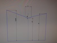
So I got this part I'm supposed to make, but the drawing is missing some information, Which I don't know how to calculate. Maybe you guys can help me out, if it's even possible..
I need to know the starting point of the Z axis for the 8 mm radius, and since the radius centre isn't in between the 11 measurement, I'm kind of lost. If possible I'd also like to learn how it's done :) Thanks for the help! Oh, and the measurements of my sketch isn't correct, it's just a sketch of the principle of the problemuploadfromtaptalk1443468216123.jpg
 
d = SQRT(r^2-(1/2*chord length)^2)

"chord Length" is the "11" in your drawing. "d" is how far above the chord the center of the radius is.

so "d" would be SQRT(8^2 - 6.5^2) which is equal to SQRT(64 - 42.25) = 4.664
 
So I got this part I'm supposed to make, but the drawing is missing some information, Which I don't know how to calculate. Maybe you guys can help me out, if it's even possible..
I need to know the starting point of the Z axis for the 8 mm radius, and since the radius centre isn't in between the 11 measurement, I'm kind of lost. If possible I'd also like to learn how it's done :) Thanks for the help! Oh, and the measurements of my sketch isn't correct, it's just a sketch of the principle of the problemView attachment 150394

The drawing does not add up and is not fully "constrained". There is a geometric conflict and would be good to ask the person who made this drawing what the design intent was...? Basically looks like a different arc or parabola is required or two different radii with reference to the lowest point of the indicated radius to join up correctly to that larger diameter. Interesting the drawing seems to indicate an appreciation of that possible geometric reality :-)That 11mm dimension seems to indicate also that the geometry has been partially "flipped" (as an additional error)Or there is an undercut that is not indicated.

I am guessing these measurements were taken in the "Field" from an existing piece... That can't be brought into the "Shop"...

Try making a scale drawing ... sketching it out to the client using a compass or circle guide and ruler to explain what the problem is and ask what is really intended here?

There's so much that's missing as there are a lot of assumptions too... For example is the part tapered or cylindrical?


Good luck :-)
 
Assuming your drawings are accurate and the 8 mm radius is true, your drawing is incomplete. A quick look at the geometry puts the centerline of the radius at the same elevation as the 50 mm surface. That implies the center of the radius is 8 mm from the edge of the 50 mm surfacee. That leaves only 3 mm of opening for the remainder and the opposite side is 5.5 mm higher. Something is not right or the information is incomplete.
 
My math shows the first half of the rad to be 6.929mm long in Z, and the 55mm OD side will be longer yet.
Doesn't appear to equate to me.


edit - 2nd half @ 7.901mm long

Makes the length of the rad @ 14.83mm long, not 11.

Gunna hafta decide whether you want 42mm ID, 8mm rad, or 11mm length.


----------------------------

Think Snow Eh!
Ox


How do you calculate that? My sketch is not exactly accurate in relation to the real drawing, but it's basically like that. It's very possible that it just doesn't add up. It happens quite a lot ^^ however I'm interested in how you came to those conclusions?
 
How do you calculate that? My sketch is not exactly accurate in relation to the real drawing, but it's basically like that. It's very possible that it just doesn't add up. It happens quite a lot ^^ however I'm interested in how you came to those conclusions?


Well, ass_u_ming that the 50 and 55.5 OD's are strait and parallel,

Your 42 is 4mm under the surface of the 50.
Your hippopotimus is 8, and since the lower apex of the rad is 4mm below the surface, we can ascertain that the center of an 8mm rad is 4mm above the surface eh?

So, 8x8 -(4x4) = X @ sqr rt. (sum of the squaws)

Repeat for side 2.


Blue's version could possibly work too. :)


Look in your Machinery's Handbook for "Solutions to a Right Triangle".
(Or buy a CAD program like everyone else here did.)


---------------------------------

Think Ptha .... Ptha ... ptha ... aw forget it .... :o
Ox
 
Last edited:
I don't think there is enough information to solve this problem.

The biggest question I have - Is that chord length measured on cardinal directions, (X distance only, or is it slanted).
I am guessing it is measured in only the x direction, but it is never smart to just get the ruler to eyeball stuff when looking at prints...

Also, distance from the outside object to the center of the circle and an angle of at least one of those sloped sides would do it... I think?

Because those upper surfaces are angled down (and not the same, from the looks), the chord length of 11 does not necessarily have to be symmetric about the vertical line that runs through the centerpoint, and it is probably not. (exaggerate the slope of those two angled surfaces to see what I mean - the chord length rotates around the centerpoint to adjust.)


If you wanted to do it paper and pencil style, I bet its going to end up in some yucky quadratic equation. something along the lines of "solve for where sloped line 'A' intersects circle 'c' "

I would draw it up in a CAD program with those missing bits of information and ask the computer where that radius starts and the slanted sides stop.
 
So I got this part I'm supposed to make, but the drawing is missing some information, Which I don't know how to calculate. Maybe you guys can help me out, if it's even possible..
I need to know the starting point of the Z axis for the 8 mm radius, and since the radius centre isn't in between the 11 measurement, I'm kind of lost. If possible I'd also like to learn how it's done :) Thanks for the help! Oh, and the measurements of my sketch isn't correct, it's just a sketch of the principle of the problemView attachment 150394

Take a class, specifically Basic Drafting. After that, you should be able to explain the problem.
 
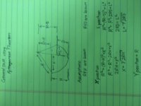
A method to find center of radius

pyth.JPG

This is a general method making no assumption about the radius other than the center is higher than the exit points.
 
simple as pie. You know three points on the circumference on the arc, right? The top left edge, the top right edge, and the bottom at the center.

Using the equation R= sqrt ((Xc-X1)^)+((Yc-Y1)^)
R= sqrt ((Xc-X2)^)+((Yc-Y2)^)
R= sqrt ((Xc-X3)^)+((Yc-Y3)^)

where R is the radius, (which you already know, but it doesn't matter) Xc, Yc is the center of the radius, X1Y1, X2Y2, and X3Y3 are the three points on the circumference.

Then it's just simple junior high school algebra to solve
 
I don't think there is enough information to solve this problem.

The bilittlequestion I have - Is that chord length measured on cardinal directions, (X distance only, or is it slanted).
I am guessing it is measured in only the x direction, but it is never smart to just get the ruler to eyeball stuff when looking at prints...

Also, distance from the outside object to the center of the circle and an angle of at least one of those sloped sides would do it... I think?

Because those upper surfaces are angled down (and not the same, from the looks), the chord length of 11 does not necessarily have to be symmetric about the vertical line that runs through the centerpoint, and it is probably not. (exaggerate the slope of those two angled surfaces to see what I mean - the chord length rotates around the centerpoint to adjust.)


If you wanted to do it paper and pencil style, I bet its going to end up in some yucky quadratic equation. something along the lines of "solve for where sloped line 'A' intersects circle 'c' "

I would draw it up in a CAD program with those missing bits of information and ask the computer where that radius starts and the slanted sides stop.

I'm sorry, they're not suppossed to be sloped. I did the sketch while on a running train so it's a little sloppy.
 
OK then:

So - is it round and these are diameters?
Flat and has an obtuse recessed corner like Blue just posted?

Can you scan and post the drawing?


Obviously you are reading replies here that we are guessing at your app.
YOU happen to be in a position to at least answer some of our assumptions....

:toetap:


-----------------------------

Think Snow Eh!
Ox
 
So I got this part I'm supposed to make, but the drawing is missing some information, Which I don't know how to calculate.

I'm sorry, they're not suppossed to be sloped. I did the sketch while on a running train so it's a little sloppy.

The reason you are getting a lot of heavy trig responses is you posted this question in the CNC section instead of down in the Mazak section.

Unless you have the Z position for the center of the 8mm radius, there is not enough information to give the machine in order for it to calculate the start or end points you need.
 
OK then:

So - is it round and these are diameters?
Flat and has an obtuse recessed corner like Blue just posted?

Can you scan and post the drawing?


Obviously you are reading replies here that we are guessing at your app.
YOU happen to be in a position to at least answer some of our assumptions....

:toetap:


-----------------------------

Think Snow Eh!
Ox

Larry, Bruce, Ox,

Your help is greatly appreciated! Thank you. Best regards.

It is round, it's an excerpt of a drawing of a piston rod (I think it's called?) And those are diameters yes. And flat, yes. And I'm sorry, I can't get the drawing since I'm away from work until Saturday, also that part will be long gone by then and I won't be able to get the drawing. I could ask the design engineer to track it down monday nw though. He should have it saved up. Interestingly, he easily could have pointed out this stuff on the drawing so it would be fast and easy to program it..


Back
Top