How to install the app on iOS
Follow along with the video below to see how to install our site as a web app on your home screen.
Note: This feature may not be available in some browsers.
Largest Manufacturing Technology Community on the Web
Stay Connected:
You are using an out of date browser. It may not display this or other websites correctly.
You should upgrade or use an alternative browser.
You should upgrade or use an alternative browser.
CNC Milling - Large Hole
- Thread starter NX - CAM
- Start date
- Replies 30
- Views 6,041
scadvice
Titanium
- Joined
- Jan 16, 2009
- Location
- "Stuck in Lodi", Ca
It depends on the machine, tool cutter, material and true position really. i.e The machine's ability to hold position from center reference, cut round and square to the surface, plus make the transitions at the quadrants. The side wall is most likely going to be a little cone shaped even with a perfect tool and .03 mm taper over the 25 mm is not much to play with plus it's hard to measure all that on the machine.
We have built a custom boring tool to do that sort of job. A large thick disk (Alum)with the Cat taper turned on it and then bored a hole near the edge, split it and tapped in bolt to pull it tight to the head's upper body, clearance slot for the adjustment socket cap and back of it during adjusting. Then balanced the whole thing for the spin.
Roughed it out to three thousand with the endmill then...Hand loaded custom head each time. Kinda scary but it worked fine and was a lot of work to make.
RC Mech
Stainless
- Joined
- Jul 21, 2014
- Location
- Ontario, Canada
You'd be hard-pressed to find a mill that could hold six tenths over 4 quadrants. The above idea wrt going in with a boring tool and not worrying about milling in the x/y plane. Skimming is difficult- if the cut doesn't load the insert it wants to rub and deflect the holder. You have a method to gauge this bore?
Edit: 90 mm? In what universe is this a "large" hole? The only reason I clicked on this thread was because you mentioned milling a large hole. 90 cm would have been 35", an actual decent-sized bore.
Edit: 90 mm? In what universe is this a "large" hole? The only reason I clicked on this thread was because you mentioned milling a large hole. 90 cm would have been 35", an actual decent-sized bore.
Vancbiker
Diamond
- Joined
- Jan 5, 2014
- Location
- Vancouver, WA. USA
You'd be hard-pressed to find a mill that could hold six tenths over 4 quadrants. The above idea wrt going in with a boring tool and not worrying about milling in the x/y plane. Skimming is difficult- if the cut doesn't load the insert it wants to rub and deflect the holder. You have a method to gauge this bore?
Edit: 90 mm? In what universe is this a "large" hole? The only reason I clicked on this thread was because you mentioned milling a large hole. 90 cm would have been 35", an actual decent-sized bore.
I've worked with several Makinos and a Yasda that could hold the OP's tolerance on a 90mm bore. You're not going to be using inserted tools on that.
scadvice
Titanium
- Joined
- Jan 16, 2009
- Location
- "Stuck in Lodi", Ca
You'd be hard-pressed to find a mill that could hold six tenths over 4 quadrants. The above idea wrt going in with a boring tool and not worrying about milling in the x/y plane. Skimming is difficult- if the cut doesn't load the insert it wants to rub and deflect the holder. You have a method to gauge this bore?
Edit: 90 mm? In what universe is this a "large" hole? The only reason I clicked on this thread was because you mentioned milling a large hole. 90 cm would have been 35", an actual decent-sized bore.
Sorry, I also was thinking of a larger bore like about 200 mm for the custom boring tool. Not sure how I missed that. Milling a 25 mm deep hole can be a little tricky at times for the same reasons I mentioned above. A standard boring head should take car of a 90 mm hole.
precisionmetal
Stainless
- Joined
- May 16, 2005
- Location
- CA
NX-CAM,
As other have mentioned, 90mm is not a large hole. Also, are you wanting to hold *size* to ±15µm or roundness to ±15µm or both? Regarding the 25mm depth, is it the 25mm you are wanting to hold to ±15µm, or the bore being straight within ±15µm?
That said, A machine that can hold 15µm on a 90mm bore should also be able to hold that on a considerably larger hole (though other issues like temperature control and how the part is held will probably influence a larger part to a much greater degree).
Is it possible? Of course. How much would you like to spend to accomplish that? Those numbers could probably be held on a Haas or Fanuc or a number of machines on an aluminum or mild steel part. Jump up to something harder, or maybe Inconel or titanium, and now there's a decent chance that a lot stiffer machine is required, especially if you want to do it in production day after day.
As with many questions posted here, the more specific and detailed you can be with your question(s), the easier it is for the participants in this group to answer your questions.
")
PM
As other have mentioned, 90mm is not a large hole. Also, are you wanting to hold *size* to ±15µm or roundness to ±15µm or both? Regarding the 25mm depth, is it the 25mm you are wanting to hold to ±15µm, or the bore being straight within ±15µm?
That said, A machine that can hold 15µm on a 90mm bore should also be able to hold that on a considerably larger hole (though other issues like temperature control and how the part is held will probably influence a larger part to a much greater degree).
Is it possible? Of course. How much would you like to spend to accomplish that? Those numbers could probably be held on a Haas or Fanuc or a number of machines on an aluminum or mild steel part. Jump up to something harder, or maybe Inconel or titanium, and now there's a decent chance that a lot stiffer machine is required, especially if you want to do it in production day after day.
As with many questions posted here, the more specific and detailed you can be with your question(s), the easier it is for the participants in this group to answer your questions.
PM
Dia 90±15µm mm is NOT a large hole !? TO MILL !?
If is not I am happy,
If you take the question out of context, then indeed, it is not at all.
But I was asking to MILL it, with a Tolerance, Surface finish and Position so I can put a Bearing in.
I need even a Dia 200 ±75µm Position 0.015 A B Depth 75±0.5
I believe this one is large !
If is not I am happy,
If you take the question out of context, then indeed, it is not at all.
But I was asking to MILL it, with a Tolerance, Surface finish and Position so I can put a Bearing in.
I need even a Dia 200 ±75µm Position 0.015 A B Depth 75±0.5
I believe this one is large !
NX-CAM,
As other have mentioned, 90mm is not a large hole. Also, are you wanting to hold *size* to ±15µm or roundness to ±15µm or both? Regarding the 25mm depth, is it the 25mm you are wanting to hold to ±15µm, or the bore being straight within ±15µm?
That said, A machine that can hold 15µm on a 90mm bore should also be able to hold that on a considerably larger hole (though other issues like temperature control and how the part is held will probably influence a larger part to a much greater degree).
Is it possible? Of course. How much would you like to spend to accomplish that? Those numbers could probably be held on a Haas or Fanuc or a number of machines on an aluminum or mild steel part. Jump up to something harder, or maybe Inconel or titanium, and now there's a decent chance that a lot stiffer machine is required, especially if you want to do it in production day after day.
As with many questions posted here, the more specific and detailed you can be with your question(s), the easier it is for the participants in this group to answer your questions.
PM
plastikdreams
Diamond
- Joined
- May 31, 2011
- Location
- upstate nj
What material? Large holes are large, 200mm is getting there, but really this is nothing too outlandish for most any decent CNC machine.
What is large to some is small to others. Some people work on stuff that is very tiny, some people work on stuff that is very large.Dia 90±15µm mm is NOT a large hole !? TO MILL !?
If you have a shitty Tormach, 90mm is probably a large hole.
If you have an Okuma, Mori, Mazak, etc... 90mm is nothing.
Ok, I got it with size, understood.
I would like to understand (if an example of Machine/Tool is possible) how to MILL Diameter 90 ±15µm , Position 0.015 A B, Surface Finish 1.2 to Dept 25 ±0.1 for a Bearing Pocket. I understand in LATHE but how the TOOL MILL will interpolate to such a Precision ?
I would like to understand (if an example of Machine/Tool is possible) how to MILL Diameter 90 ±15µm , Position 0.015 A B, Surface Finish 1.2 to Dept 25 ±0.1 for a Bearing Pocket. I understand in LATHE but how the TOOL MILL will interpolate to such a Precision ?
hanermo
Titanium
- Joined
- Sep 28, 2009
- Location
- barcelona, spain
Vastly better accuracy is available.
Mori demonstrates milling a bearing pocket with interpolation on their high-end DCG machines to 0.7 microns accuracy in TIR.
Video online on youtube.
As others said anything modern will do 90 mm diameter to +/-15 um or 90.000 +/- 0.015 mm in easily machining steel via interpolation.
But it might take a fair bit of experimentation wrt the right tooling, and depth cylindricity etc.
So it is perfectly doable, but the tooling may or may no be trivial, depending.
mhajicek
Diamond
- Joined
- May 11, 2017
- Location
- Maple Grove, MN, USA
A new Haas that's been ballbar and laser calibrated can do it easy if you treat it right. I'm sure it should be trivial for a higher end machine. It's that calibration that's key, along with not having wear and slop in your ways and screws.
DMF_TomB
Diamond
- Joined
- Dec 13, 2008
- Location
- Rochester, NY, USA
.It is possible to Mill a Large Diameter Hole with high precision of +-0.015 (mm) ?
For example for a Bearing Pocket : Dia 90 +-0.015 depth 25 !
For about this precision (if possible), what would be the max acceptable diameter ?
.
normally would use a indicating bore gage to measure out of round and hole taper.
.
in general that tolerance you would use a boring bar
+/-.0001" (.0025mm)on bore up to 150mm are done often
.
depends on length to dia ratio of boring bar. long small dia boring bars cannot hold tight tolerance and surface finish is rougher due to vibration. 4 to 1 not bad but 5 to 1 length to dia start to have problems
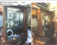
Attachments
NX-CAM why don't you try it, then when it isn't right come ask questions. NOT just ask "is this possible?" Of course it's possible. We have no idea what you are doing what A and B are, what machine, what tooling, what anything.
Tired of these posts guys, try it man!!! User name NX-CAM indicates a working knowledge of arguably to best CAM software on the market, but you don't know if you can Mill a hole? Or that "Big" is relative?
R
Tired of these posts guys, try it man!!! User name NX-CAM indicates a working knowledge of arguably to best CAM software on the market, but you don't know if you can Mill a hole? Or that "Big" is relative?
R
DMF_TomB
Diamond
- Joined
- Dec 13, 2008
- Location
- Rochester, NY, USA
most likely you have never had 250. mm bore out of round enough you could not get 100 kg parts to fit together and be able to rotate part to line up the bolt holes.
.
.02mm out of round can easily need hammer to get parts apart as when rotated the out of round on 2 mating parts locked up tight needing a hammer to get apart.
.
most people measure each and every circular milled bore. also normal even on bored holes when part is unclamped many parts and their bores go out of round
.
.02mm out of round can easily need hammer to get parts apart as when rotated the out of round on 2 mating parts locked up tight needing a hammer to get apart.
.
most people measure each and every circular milled bore. also normal even on bored holes when part is unclamped many parts and their bores go out of round
Is A Perpendicular to B? Is A a straight line, a hole, a chamfer, a pitch diameter, is B a figment of some ME's imagination? What do you think, every print has the same Datums?
But no I do not understand what
I'm trying to help you get a real answer my friend. I do in fact understand. So to answer your question; Yes!! We've been doing stuff like this for a really, really long time. There is more to it than can I do it.
R
But no I do not understand what
means.Department 25±.1
I'm trying to help you get a real answer my friend. I do in fact understand. So to answer your question; Yes!! We've been doing stuff like this for a really, really long time. There is more to it than can I do it.
R
I do not believe that this is an appropriate behavior here.
I have 15 years of working with GD&T
Dia Position to A B mean in this case, Dia is perpendicular to A and Concentric to B
I was refering to depth
And you do not have to answer, if you do not understand, please do not answer
Thanks
I have 15 years of working with GD&T
Dia Position to A B mean in this case, Dia is perpendicular to A and Concentric to B
I was refering to depth
And you do not have to answer, if you do not understand, please do not answer
Thanks
Is A Perpendicular to B? Is A a straight line, a hole, a chamfer, a pitch diameter, is B a figment of some ME's imagination? What do you think, every print has the same Datums?
But no I do not understand what means.
I'm trying to help you get a real answer my friend. I do in fact understand. So to answer your question; Yes!!
R
I do not believe that this is an appropriate behavior here.
I have 15 years of working with GD&T
Dia Position to A B mean in this case, Dia is perpendicular to A and Concentric to B
I was refering to depth
And you do not have to answer, if you do not understand, please do not answer
Thanks
The problem is that you're not giving us enough information.
Don't get mad at the people here because of that.