What's new
What's new

CNC monitor replacement- Was this CRT monitor color ? (photos)

Milacron

Administrator
Staff member
Joined
Dec 15, 2000
Location
SC, USA
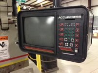
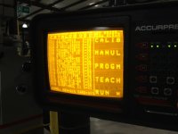
photo-96.jpgphoto-97.jpgphoto-98.JPG
1996 vintage Accurpress control. Owners think the monitor may have been color before it went to amber only*. The 6 wires at the connector hint that it probably was. (R,G,B,H,V,G is the usual minimum for color monitor wires) I've never seen a color monitor go from color to monochrome like this before however...have you ? Bottom line is, as you can see from photo the monitor still works but it's too bright and with some strange horizontal lines, so it may go out completely any day. I adjusted the brightness and contrast pots and it made no difference whatsoever.

Naturally the control maker wants an outrageous sum for replacement and the user can't spare the downtime to have it fixed. The ideal would be to know if for sure it is getting color signals and what exactly is the H (horizontal) frequency so it could be replaced with LCD.

If it was in my shop I could tell with a frequency meter but it's 50 miles away and not my machine.

========================================================

*(on edit) I just Googled Accurpress control, images and found only two images of the same control. Both of them have monochrome amber displays. This indicates the owners are probably having a false memory of how it used to be. Then again, why would a monochrome monitor have 6 signal wires ?? I wonder if it's like many controls in the mid 90's where the monitor is monochrome but the control is supplying color signals for either an optional color monitor or the color monitor that would be standard the very next year ? I have had Bridgeport CNC mills for example with monochrome monitor but when replaced with color LCD they did display in colors and looked quite nice.


In the second picture there are two heavier conductors, which would suggest they are power supply. That leaves four signal - not enough for RGBHV, but it could still be composite sync, or sync on green. The small green cable has something piggybacked on it, which might be a clue. If it is composite/sync on green you're going to require one of the expensive built-for-purpose panels, or a converter. I have one of these and it does support both.

I don't think it would be a big leap to say that it's a colour CRT, going by the visible labels on the board.

As for why it's amber, very confusing. Is it possible that the control is outputting RGB but is just colouring everything amber? Parameter issue?
 
In the second picture there are two heavier conductors, which would suggest they are power supply. That leaves four signal - not enough for RGBHV, but it could still be composite sync, or sync on green. The small green cable has something piggybacked on it, which might be a clue. If it is composite/sync on green you're going to require one of the expensive built-for-purpose panels, or a converter. I have one of these and it does support both.
the small green cable with another cable is ground. The two heavier conductors are a curiosity as there is another cable (not shown in photos) for the power supply. I figured they were H and V but there is no reason for horizontal and vertical wires to be larger that the RGB wires really...so dunno...makes no sense.
 
monitor pinout

pinout.jpg

Not sure it will help; this is the pinout for the 10 slot card edge connector I am familiar with on monitors dating to the mid 80's Dynamic Displays in Eu Claire WI might be able to help.
 
View attachment 124265

Not sure it will help; this is the pinout for the 10 slot card edge connector I am familiar with on monitors dating to the mid 80's Dynamic Displays in Eu Claire WI might be able to help.
Wow...that must be it...that explains the larger wires are power supply related sure enough. Apparently the other cable I mentioned was the "in" to the power supply and pin 7 and 1 are the "out" from the power supply to the signal board. Thanks !
 
If that is the 9" screen, the default was amber. IIRC, there was option of green instead.
Users are telling me that the monitor text was green before it started looking screwy as now. Is that possible ? Where exactly does the green or amber originate...in the CR tube itself or in the signal board ?

I've changed many CNC control color CRT's to color LCD but never messed with changing out a monochrome CRT before.....can a color LCD (TFT) be subbed here (to display in mono, obviously) if the horizontal freqency is high enough ? Or is another working mono CRT the only choice ?
 
Users are telling me that the monitor text was green before it started looking screwy as now. Is that possible ? Where exactly does the green or amber originate...in the CR tube itself or in the signal board ?
It's a mono tube so the color comes from the tube phoshor. The tube itself was available in amber, green or white. For some reason the white variant was not available on that control.
 
It's a mono tube so the color comes from the tube phoshor. The tube itself was available in amber, green or white.
Interesting...that's what I suspected...so the user has to be having a false memory on it previously displaying text in green.
 
Interesting...that's what I suspected...so the user has to be having a false memory on it previously displaying text in green.

Unless there was a green filter over the screen.

3M made polarizing filters that could change the color.
white->green
white->amber
amber->green
 
I replaced a mono CRT with color TFT on a Supermax with mits control a few months back. The orig was Amber the new one is green not a big deal. A few small issues with lettering looking a bit funny in a couple places due the the difference in resolution but not bad. I used a kit that has a built in converter and costed around 400 or so.
 
I recently successfully replaced a mono CRT with a color LCD in an AB8600. The LCD had a built in A/D converter that could detect the sync frequency. It turned out the frequency was out of range for the converter to lock-in. I sent it back to the supplier and they rewrote the firmware at no charge. Upon receipt, it worked when I plugged it in. They even put the correct input connector on. Money well spent with Dynamic Displays!
 
Accurpress ap2 crt to lcd conversion

I'm glad I found this thread as I have been dealing with a burnt out monochrome crt tube on my accurpress ap2 control for months now! I have spent a lot of time trying to source a new screen. I did not want to replace it with another tube, I wanted to convert it to lcd. The factory does offer a lcd replacement for this, but the price is way out of the realm of reality. Every accurpress ap2 control I have ever seen (lots) has had the amber coloured screen. The video signal output from the card is called MDA. The plug is a standard db-9 also know as a rs-232. I tried a few of the TFT monitors that are said to work on the 9 pin plug, and are all one unit. These did not work! good thing they were returnable.

Ok, now for what DOES work! The XVGA box (GBS-8219) readily available online will auto scan and convert the 9 pin signal to a VGA output that will display on ANY lcd monitor with a VGA input.

The xvga box comes with everything required to make the switch, except for the monitor. The 9 pin wire that comes with the xvga box is only half complete and will need one end soldered. This is not that hard, I am not an electrician, I am a millwright, and not a techie one either. You could skip the soldering by purchasing a ready made db-9 (rs-232) cable with two MALE ends

If you want to tackle the solder job, Here are the correct pin outs to make it all work

PIN 1 solder the BLACK wire to pin 1 of the supplied MALE connector
PIN 7 solder the BROWN wire to pin 7
PIN 8 solder the YELLOW wire to pin 8
PIN 9 solder the WHITE wire to pin 9

All other wires are not used.

The soldered wire goes between the Accurpress control box, and the XVGA box. You then connect a standard VGA cable from the XVGA box to the monitor of your choice, plug the whole works in, and you are all set! use the menu function on the XVGA box to fit the image to to use the full screen and you are done.


accurpress ap2 crt to lcd conversion.jpg
 
As an update to my previous post, I found a ready made db-9 cable and tried plugging it in. For some reason it did not work. I am not sure why this is, it should work, but it didn't. It works fine with the soldered wire.
 
As an update to my previous post, I found a ready made db-9 cable and tried plugging it in. For some reason it did not work. I am not sure why this is, it should work, but it didn't. It works fine with the soldered wire.
The wiring is non-standard. A standard VGA cable does not have pin-9 connected.

Glad to see you got it working.
 
Hello.
I have a CNC lathe that has a monitor very similar to what I found here on this topic.
The image is getting harder and harder to read.
I was researching a way to swap for an LCD monitor.
The monitor pinout is the same as the brucecu posted in post # 4.
But I have only 4 wires connected to the board.

pin 1 - system ground (checked with the multimeter)
pin 2 - not connected
pin 3 - not connected
pin 4 - not connected
pin 5 - not connected
pin 6 - not connected
pin 7 - 12V (checked with the multimeter)
pin 8 - Video input (15khz checked with multimeter)
pin 9 - not connected
pin 10 - system ground (checked with the multimeter)

vertical and horizontal inputs are not connected.

Do you think the XVGA box quoted by willisworm will work? Is there any other cheaper way to connect the monitor to the lathe control?


CNC Monitor (1).jpg
CNC Monitor (2).jpg
CNC Monitor (3).jpg
CNC Monitor (4).jpg
CNC Monitor (5).jpg
 
Hello
Help schematic
Separate H (horizontal), V (Vertical) signals from the video signal
 

Attachments

  • IFD2598_F1_WEB.jpg
    IFD2598_F1_WEB.jpg
    28 KB · Views: 632


Back
Top