What's new
What's new

Fadal coolant outlets voltage issues

Cferrell84

Plastic
Joined
Mar 5, 2016
Fadal vmc15 I'm having issues with my coolant outlets (flood and mist). They both have 109-110v output constantly and when I type m7 or m8 at the mdi prompt they both go up to 120v but when I type a m9 they only drop to 109v. I plugged up a lamp to the flood outlet and it barely lights up and flickers a bit when it's supposed to be completely off and comes on when m8 is entered. Could both the relays beside the fuses be bad?
 
Are you sure it is a mechanical relay/contactor used to switch the receptacle? Sounds like maybe leakage through a solid state device. Did your lamp test use an LED bulb or was it an incandescent bulb? You might need to repeat your test with something with a slightly bigger load.

Did the coolant pumps ever work for you before or is this machine new to you. These outlets may have a very low current capability and a triac/SSR could have been damaged by a previous owner. Check on the control signal side of the switching device to determine if that is functioning properly. That would tell you if it is the switching device or something deeper in the control. Pics or a schematic might help.
 
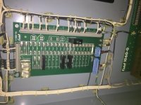
image.jpgimage.jpgimage.jpgimage.jpgI was using a fluorescent bulb in a standard table lamp. Soon as the machine powers up it starts flickering and has 109v going to it all the time till m8 is entered
This is a new to me machine I haven't been using the coolant since I dry cut most of what I do but was trying to get it set up for use as air blast
I'll get some pics and schematics
 
The grayhill relays are beside each fuse position. F18 is mist(fuse missing in pic). F22 is flood and relays for each are right beside them.
 
Those are solid state relays and what you are seeing is current leakage. Using any type of florescent light as a test light with this circuit will be erroneous.

If you want to check the leakage current put a 250ohm resistor across the two 120V lines and check what the voltage is across the resistor. Voltage/resistance will equal leakage current. You will probably get a very low voltage drop and leakage current.
 
Yes that is a solid state relay or technically a triac inside, not a mechanical contact like the symbol on the case might suggest to you. What you are measuring with your volt meter is probably the result of some leakage current. Try using a lamp with say a 60 or 75 watt incandescent light bulb. As you can see on the label, these solid state relays are only good for 3 Amps maximum, so your coolant pump can only be a small one, say like one of those little giant plastic jobbies. If you want to use something more substantial, you could use the SSR output to drive a motor starter (contactor and overload) for a 3 phase pump that provides enough pressure for a wash down hose etc.

I wouldn't recommend you do the 250 ohm resistor thing mentioned above for two reasons: 1. At your experience level, I don't think it really serves you to know specifically what the leakage current is. 2. If the solid state relay is shorted or damaged or you turn on that specific M code to activate it you will be sinking 60 watts of power through the resistor and it will instantly go poof and let the magic smoke out of the typical Radio Shack variety 1/4 or 1/2 watt resistor you are likely to get your hands on.
 
Ok well my main objective for now is to install an air blast using the mist or coolant output. I have a 120v normally closed air solenoid I'll have to Che k if it says what Amps it draws. What if anything do I need to do to make it work? I haven't plugged it in yet to either of the outlets to see what it did I just assumed it would probably partially open soon as the machine powered on
 
Ok so I just spoke with a Fadal service tech and apparently it is perfectly normal for the Fadal coolant pump outlets to have 109-110v going to them even when not activated. I hooked up my air blast solenoid and it's staying closed and opening when m8 is entered and closing back with an m9 so apparently all is well. I never would've thought there should be voltage going to the outlets even when there supposed to be off
 
Those particular SSRs have an internal snubber circuit built in to protect it from transient voltage spikes when the solenoid valve's coil collapses. As long as you have a properly sized fuse on the load to protect your $20 SSR from short circuits you should be fine. You may find that your P/N 1100 relay board can be populated with the spare SSRs you purchased for some additional M code enjoyment. I don't know, Fadal controls might have the extra M codes locked out by some sort of paid parameter option that has to be typed in. I know Fanuc does that alot.
 
On my schematic it has 6 or so M codes tied to fused relay outputs, something like M60 and onward.

I haven't investigated it any more than what's on the schematic, which in itself is useless for understanding how the machine is wired.
 
Yeah I think the m60's are spares but according to how I read the schematics (yes somewhat useless) they are not connected to anything. I know you have to install a 1050-3 m code card to install something like a haas rotary indexer with the separate control box

I have been looking into this because I figured since they were spares I could wire in the control box to them but the schematics don't show where they go and everyone has said it has to have the extra m-code card to hook up an indexer box


Back
Top