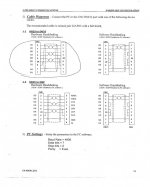
This morning I reworked the cable for "software handshake" and the pin out (with Fanuc on the left) is:
2 - 2
3 - 5
1 and 7 - 5 (Note: this is the bare wire)
At the Fanuc end, 4 and 5 are jumped; 6, 8, and 20 are jumped
At the PC end, 1, 4, and 6 are jumped; 7 and 8 are jumped.
I confirmed that parameter 391.6 is 0
With this configuration, I can't either send or receive. Both trigger the 086 P/S alarm.
What other settings and parameters should I look at?
Hi Hoppy,
The following pin-out is correct for, and will work with Xon Xoff (Software Handshaking)
Machine Side ---------------------------------- PC Side
DB25 Male ------------------------- DB25 Female ------- DB9 Female
1 ----- Shied Trace Wire ---------- Not Connected ---- Not Connected
2 ------------------------------------ 3 ------------------- 2
3 ------------------------------------ 2 ------------------- 3
7 ------------------------------------ 7 ------------------- 5
4
| Bridged
5
6
|
8 All Bridged
|
20
Note: Jumping pins 7, 8 and jumping pins 1,4, and 6 is not necessary on the DB9 connector at the PC end; just construct the cable as shown above.
Pin one of the control's DB25 connector is Protective Ground, Pin 7 is Signal Ground. You don't connect both of these to Signal Ground at the PC end.
The other parameter settings are as follows:
#0002
Bit 0 = 1
Bit 2 = 0
Bit 7 = 1
#552 = 10 (4800 Baud - Starting Point)
Machine Control Set Page Settings
I/O = 0
ISO Format
The PC Comms Software I/O protocol should be set as follows:
Handshake Method = Xon Xoff (Software Handshaking)
Data Bits = 7
Stop Bits = 2
Parity Bit = Even
Baud Rate = 4800 (to mach whatever the control parameter setting refers to)
If you still get a P/S 086 alarm, check with a multi-metre for => than 5VDC (normally around 12VDC) between pin 20 and Protective Ground. If not, you have issues as described in my first Post. A possible workaround is to connect pins 6 and 8 of the DB25 connector at the control end, to pin 4 of the DB9 connector at the PC end.
Regards,
Bill