What's new
What's new

Fanuc OT RS232 File Transfer and Parameter Back Up.

Kawgomoo

Cast Iron
Joined
Feb 24, 2013
Location
phoenix
Hello all, I'm back with yet another task.

I am trying to connect my old laptop to my Fanuc OT control so i can back up parameters and transfer files over from CAM.

I have been advised by other owners that backing up is of utmost importance, and i would like to get that done not knowing the age of the batteries. In an ominous sign, when i booted up my old laptop with native serial port, it has CMOS errors from a dead battery. Now I'm super on edge.

Moving forward my laptop has a native DB25 serial connector on it, running windows xp. I have tracked down the wiring pinouts for the cable, that seems straight forward enough, and i have Serial cable and DIY adapter ends here already.

I have seen some parameters listed to set the control to, but honestly i am unsure of where to locate these parameters. Much less what keystrokes to enter to actually edit them Bits, bit registers, these are all terms above my head at this time, making much of the information I've found up till now quite useless with my level of understanding.

RS232 For Dummies? i could use it.

Once i get the Control set to send and receive data, how about the pc end? Is there a guide on what software to use and how to use it?

My machine has a tape reader power outlet on the side of it that i had planned to plug my laptop power adapter into to avoid ground potential issues. Ive read this can be a thing.

Once i get this cable built in the next few minutes....where to go from here?

Thank you all!
 
Hello all, I'm back with yet another task.

I am trying to connect my old laptop to my Fanuc OT control so i can back up parameters and transfer files over from CAM.

I have been advised by other owners that backing up is of utmost importance, and i would like to get that done not knowing the age of the batteries. In an ominous sign, when i booted up my old laptop with native serial port, it has CMOS errors from a dead battery. Now I'm super on edge.

Ensure the control is turned on when changing the batteries otherwise you will loose all parameters.

Moving forward my laptop has a native DB25 serial connector on it, running windows xp. I have tracked down the wiring pinouts for the cable, that seems straight forward enough, and i have Serial cable and DIY adapter ends here already.

Unless your laptop is ancient, its unlikely to have a DB25 Serial Port. Many confuse the LTP1 connector (DB25 Female) as a Serial Port. Unless its a Male Connector, its not a Serial Port.

RS232 For Dummies? i could use it.
Not really.

Once i get the Control set to send and receive data, how about the pc end? Is there a guide on what software to use and how to use it?

My machine has a tape reader power outlet on the side of it that i had planned to plug my laptop power adapter into to avoid ground potential issues. Ive read this can be a thing.

Cable Pin-out for Xon Xoff Handshaking
Machine Side ----------------------------- PC Side

DB25 Male Connector --------- DB25 Female -------- DB9 Female
1 ---- Shield Trace -------- Not Connected ------ Not Connected
2 -------------------------------- 3 ------------------ 2
3 -------------------------------- 2 ------------------ 3
4
| Bridged
5

6
|
8 All Bridged
|
20

7 -------------------------------- 7 ------------------ 5

Note that pin 1 of the Machine DB25 connector (Protective Ground) is connected to the Shield Trace Wire, but not at the PC end. If the two devices use different Ground Sources, or either are not Grounded well, a Ground Loop could occur with both ends connected.

Control Parameter Settings:
#0002
Bit 0 = 1
Bit 2 = 0
Bit 7 = 1

#552 = 10 (4800 Baud - Starting Point)

Control Set Page Settings:

I/O = 0
Format = ISO

PC Communication Software RS232 Protocol Settings:
Handshake Method = Xon Xoff (Software Handshaking)
Data Bits = 7
Stop Bits = 2
Parity Bit = Even
Baud Rate = 4800 (or whatever the control is set to)

Once i get this cable built in the next few minutes....where to go from here?
Once you have the Cable configured and Machine Parameters set as above, you need to obtain Communication software to install on your Laptop. You could use the Hyper Terminal software that is supplied with Win XP, but you will find free, purpose built for CNC application, software on the Internet. One that is quite reliable and free is NCLink from OneCNC. After installing the software, configure the RS232 Protocol of the software as listed above.

To Output parameters from Machine to PC:
1. Select EDIT Mode
2. Set the PC Software ready to Receive
3. Press PARAM
4. Press the START Button (not the CYCLE START Button)
5. If you want to Output the Option Parameters (advisable), Press and Hold the EOB Button before pressing the START Button in step 4 above.

The parameters will be Output to the PC

To Output all Programs from Machine to PC:
1. Select EDIT Mode
2. Set the PC Software ready to Receive
3. Press the PRGRM Button
4. Key in O-9999
5. Press the START Button

All programs registered in Memory will be Output to the PC

If the control has Macro Programs registered in the program range O9000 to O9999, Bit 4 of parameter 0010 has to be set to "0" to allow these programs to be Output. If you take this step, ensure that Bit 0010.4 is set back to "1" to protect these programs from deletion. It is advisable to save a copy of all Macro Programs.

Regards,

Bill
 
Last edited:
Thank you bill!

I believe the last half of that post was the information i was missing!

My laptop is in fact ancient. {How long does it take for a CMOS battery to die?} This laptop is kept around specifically for its native DB25 Serial Port. This laptop is used solely for RS232 communication with Automotive Engine Management Computers in my "real life". However, the software they supply is much more user friendly. Select the comm port and you are in. The rest is handled through GUI making it pretty well dummy proof.

Its an IBM Winbook built around the same time as my lathe was built :D

I have been advised not to mess with the battery at all until i can back up the param's. And have also been advised about having the machine powered up when the change is made so i don't brick the control.

Thanks very much! This is an outstanding resource, a wealth of knowledge i would truly be lost without!
 
To add to Bill's excellent info: on my Fanuc machines, I use a Belkin F2L088-01 cable and a null modem. Also use a DOS based program called CNCCOM, supposedly written by a Fanuc USA tech sometime in the early '80s. Works great on my 486DX DOS6.1 computer. If you would like, I can send you a copy of the CNCCOM program.
 
My computer has a DB25 Serial connector, not a 9 pin.

I assume most the people with the 9 pin are using a PCMCIA/adapter card to get a serial port.

Ive got a diagram for the db25-db25 null modem, which uses what i assume is a hardware handshake. Most the CNC specific info is bridging those lines together for a sort of fake shake.

Ill surely take a look at that software. I'm not too handy with dos commands...its been a while! lol.

But that relates to my next question. HOW do i prepare the PC to talk to the Fanuc control. Aside from hardware settings, what next?

I assume my G code will post to a .txt file from CAM , and i push that over from the PC. But how exactly?
 
Give me an email address and I will send you the program, cnccom.zip.

0T:

To receive program from PC:

1. Open communication program on PC
2. Select program to send to machine
3. select edit on machine
4. type in program number you want to use
5. press input button. If LSK appears and flashes, then machine has found and recognizes PC
6. press appropriate button on PC to start sending program to machine.

That's it. When program is transferred, the program will show up on the machine display.

To send program to PC:

1. Open communication program on PC
2. select receive function
3. Select location to place program
4. press appropriate button to begin to receive
5. select edit on machine
6. type in program number to send
7. press "output/start" button (the green button on the keypad with the letters, numbers, blue function keys.)
 
i happen to have a Frys Electronics right across the street from my house, the null modem db25-db25 connectors are only 3 bucks. Cheaper than digging out the soldering station!

They have three flavors of null modem.

Null Modem No Handshake.
Null Modem Full Handshake.
Null Modem.

Which of the three is the correct choice? Or none, stop being so lazy and wire the one up myself? :) {i have a tendency to fry electronics, I'm hesitant here} My diagrams match perfectly the one bill posted to "loopback handshaking" but thats not one of the options from Frys. lol. grrr.
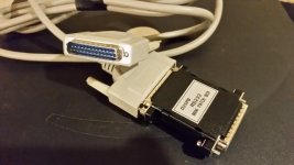
 
Or none, stop being so lazy and wire the one up myself?

That will work.

When called to solve a comms issue between machine and external device, when the client has supplied the cable, either store bought finished, or the parts and they've made it themselves, the first thing I do is establish if the pin-out is correct, either by removing the Back-shells (if possible), or use a Multi-metre. By making the cable yourself, you know for sure that the configuration is correct, thus taking one unknown out of the equation when establishing communication between the two devices. It should take you five to ten minutes.

When using Xon Xoff Handshaking, the cable you require is a Loop-back Null Modem cable. Null Modem is a generic term and refers to any cable where the TD(Transmit) and RD(Receive) lines are joined end for end, that is, TD to RD; accordingly, I'm not sure what you mean by the third choice, Null Modem. The three basic types are:

1. No Handshaking. This is where the TD/RD and SG(Signal Ground) at one end are connected to RD/TD and SG at the other; no other wires, or bridging is used.

2. Loop-back Null Modem Cable. This is where the RTS/CTS and the DSR/CD/DTR pins (the Control Pins) are respectively bridged, giving the illusion of Handshaking.

3. Full Handshaking. This is where the Control Pins are connected end for end and change in voltage on these lines is used to control the data flow.

Regards,

Bill
 
Thanks Bill.

I ALMOST had it built! The element in my soldering station burned out, only had #8 and 20 left to solder and woulda been GTG. Was hoping a store bought solution would get me rolling, looks like a new soldering station is coming. Tired of this cheap chinese crap. Ugh.

I will keep you posted on my progress!

Hope to have this resolved, had to turn away work today and thats cash i desperately need.
 
Alright reinforcements were called in, supply drops were made.

We now have a handy little jumper box all wired as per bills diagram above.

And away we go. This is where it gets really scary....for me. lol.

20160808_163745.jpg

20160808_163828.jpg
 
Alright i am proceeding forward.

the 110v power plug for the tape reader i had intended to use on the side of the machine has no power.

lets hope this isn't an omen of things to come.

onwards butter cup!
 
Ensure the control is turned on when changing the batteries otherwise you will loose all parameters.


Control Parameter Settings:
#0002
Bit 0 = 1
Bit 2 = 0
Bit 7 = 1

#552 = 10 (4800 Baud - Starting Point)

Control Set Page Settings:

I/O = 0
Format = ISO

PC Communication Software RS232 Protocol Settings:
Handshake Method = Xon Xoff (Software Handshaking)
Data Bits = 7
Stop Bits = 2
Parity Bit = Even
Baud Rate = 4800 (or whatever the control is set to)

Bill, I can not locate "Format = ISO" in the control.

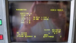
I am also unsure how to change the "bits" in parameter line 0002. Just to make sure following the photo all i need to do is change the first bit to a 1 and I'm good? So it read "0002 10000001"?

I think the other settings look good from as far as i can tell.

Please advise. Thanks greatly!

20160808_184650.jpg
20160808_184741.jpg
20160808_185321.jpg
 

Attachments

  • 20160808_190140.jpg
    20160808_190140.jpg
    97.7 KB · Views: 2,072
ISO is good. Its the second setting down in your picture


ISO =1
View attachment 177626
[/QUOTE]


Yeah i figured that was good after staring at it a bit. It seems 1 = Enable for ISO so that made sense.

I still can't figure out how to change the 0002 bit, or if I'm even in the right spot. i hit the dgnos/param key once, the page down and I'm there. But it doesn't respond to any presses of the keypad at that point
 
That is the correct parameter and page. Their will be a way to edit parameters then after you change 0002 parameter to what you need, then you would set it back to how it was. That is so parameters can't just be edited easy.
 
1) Preparation
(A) Select the MDI mode.
(B) Press the function button [DGNOS/PARAM] to display the
parameter setting screen.
(C) Key in address “No.” and value “0” in the stated order, then press
the [INPUT] button; the setting parameter screen will appear. Set
PWE = 1.
(D) Executing the above steps enables parameter input.
2) Setting
(A) On the parameter setting screen, key in address “No.” and the
desired parameter number in the stated order, then press the
[INPUT] button. The desired number will be searched for. Using
the cursor/page key can also switch the screen sequentially.
(B–1) Bit–type parameter
Specify 0 or 1 in the 8 bits of the parameter. One parameter
consists of 8 bits. Bit 7 is the highest bit, and bit 0 is the lowest.
It is impossible to set or reset an individual bit separately from
another bit. All bits must be manipulated simultaneously.
Example)
If you want to change “00001000” to “10001000”, key in
“10001000”[INPUT].
The highest bit must be entered first, then the next highest,
and so on. The lowest bit must be entered last. If only less
than 8 bits are entered, any bit left unspecified is regarded
as 0.
Example)
“1001[INPUT]” is equivalent to “0001001[INPUT]”.
(B–2) Nonbit–type parameter
Key in a value within the valid data range, and press the
[INPUT] button.
3) Resume the setting that was changed in item 1).

!!!!MAKE SURE YOU CHANGE PWE BACK TO ZERO AFTER YOU SET YOUR 0002 PARAMETER: PWE = 0
 
Yeah i figured that was good after staring at it a bit. It seems 1 = Enable for ISO so that made sense.

I still can't figure out how to change the 0002 bit, or if I'm even in the right spot. i hit the dgnos/param key once, the page down and I'm there. But it doesn't respond to any presses of the keypad at that point

If you page on from Setting Page 1, you will find a page that has PWE (Parameter Write Enable) displayed at the top of the screen. You have to set this to 1, upon which a PS100 alarm will immediately be raised. Ignore this and navigate to the parameter you want to change. Most of the parameters are in 8 Bit format with bit Zero right most and counts towards the left to bit seven. Parameter 0552 is in Decimal Format and 10 will be registered for 4800 Baud Rate, 11 for 9600 Baud. Once you have finished setting parameters, the PWE has to be set back to "0". The PS100 alarm will persist if you call the Alarm Page. To extinguish it press Reset.

To twr,
Sorry for cutting across your reply; you made your Post whilst I was still typing.

Regards,

Bill
 
Yeah i figured that was good after staring at it a bit. It seems 1 = Enable for ISO so that made sense.

I still can't figure out how to change the 0002 bit, or if I'm even in the right spot. i hit the dgnos/param key once, the page down and I'm there. But it doesn't respond to any presses of the keypad at that point

Looking at the current setting of parameter 0002 and 0552, you will be able to Send and Receive parameters and programs how they are now. The only thing that will occur with Bit 7 set to "0" is that a string of Null characters will be Output at the Start and End of the transfer. Parameter 0552 is currently set to 4800 Baud. Accordingly, if you were to set your Communication Software to:

Handshake Method = Xon Xoff
Data Bits = 7
Stop Bits = 2
Parity Bit = Even
Baud Rate = 4800

You will be good to go.

Regards,

Bill
 
Another item that can sometimes help when working RS-232 problems is a RS-232 signal tester. It has a series of LED's that are marked to correspond to the commonly used lines such as TD, RD, etc. FRY's will have one.
FRY's number is 25573 or 140736. Can tell you which lines are getting power and if data is being sent by either device.


Back
Top