What's new
What's new

FANUC's manual for SKIP function (Used for G31) is CONFUSING!!

Stephan Spears

Aluminum
Joined
Apr 12, 2014
Location
AB,Canada
Has anyone taken a closer look at the output of G31??

In a scenario where a probe is on the machine which is currently at the position X150 Y0 Z0. Consider the following NC program,

N1 G31 X200. F1000;
N2 #1=#5061;
N3 #2=#5041;
N4 M0;

During the motion of G31, if the SKIP signal is turned on high when the machine reaches X180 physically, the machine will capture system variables #5061, #5041 and save them to #1 and #2.

When the CNC recognize the skip signal, the machine is at 180.003.
When the machine motion stops, the machine is at 182.5.
what are the outcomes of #1 and #2?

Are they
#1 = 180.003 (Current machine position when the CNC recognize the skip signal)
#2 = 182.5 (Machine position when the machine motion stops)

or
#1 = 182.5 (Machine position when the machine motion stops)
#2 = 182.5 (Machine position when the machine motion stops)
??

Thanks in advance.


Steph

First of all, in order to prevent the buffering effect, the program should look like this:
N1 G31 X200. F1000;
G53;
N2 #1=#5061;
N3 #2=#5041;
N4 M0;

The #5061 is loaded with skip (probe trigger) position coordinate (180.003). The machine continues to move and stops and its position (182.5) is loaded to #5041. G53 prevents reading the results to #1 and #2 until this process is finished. Then only the transfer to #1 and #2 is executed and they are 180.003 and 182.5 respectively.

That's what I think too. I experiemented the program and it does give me 2 different readouts.

I read in the FANUC connection manual mentioned a parameter 6201 bit 1 SEB. It says it considers the acceleration/deceleration for the measurement readout. Any idea what that means?

I attach the screen shot here and the description of that parameter is at page 1625 of FANUC manual B-64303EN-1/04.

Capture.jpg

Thanks for your help.

Steph
 
I believe, in the 2-touch method where the second approach is at a very low feedrate, this parameter will have negligible effect.
 
IME, when the second touch and the probe calibration touches are done with the same feedrate, then this does not matter. The result is the probe tip appears a different diameter than it physically is. Since that value is part of the calibration record and used in subsequent calculations, the probe results are correct.
 
IME, when the second touch and the probe calibration touches are done with the same feedrate, then this does not matter. The result is the probe tip appears a different diameter than it physically is. Since that value is part of the calibration record and used in subsequent calculations, the probe results are correct.
This is correct. This parameter is not significant when using 2 touch probing technique, as the probe is travelling practically the same distance after each back off move, and its federate is always the same when touch occurs. Contrary to that, when probing using 1 touch technique, the distance of the movement toward the touch is not known and varies.
 
First of all, in order to prevent the buffering effect, the program should look like this:
N1 G31 X200. F1000;
G53;
N2 #1=#5061;
N3 #2=#5041;
N4 M0;

The #5061 is loaded with skip (probe trigger) position coordinate (180.003). The machine continues to move and stops and its position (182.5) is loaded to #5041. G53 prevents reading the results to #1 and #2 until this process is finished. Then only the transfer to #1 and #2 is executed and they are 180.003 and 182.5 respectively.

Hello PROBE,
G31 itself prevents buffering, with G31 alone, without an axis being specified, used as a buffering preventative G Code. Accordingly, G53 in the above example is not required.

The following three examples run on a fast processing Fanuc control, will result in the value being recorded in #100 as Zero (or close to it), -100.0 and -100.0 respectively.

Regards,

Bill

Example1
O1234
N1 G91 G28 Z0.0
G00 Z-100.0
#100 = #5023
M00 (to allow viewing the result recorded in #100)
G28 Z0.0
M30
%

Example2
O1234
N1 G91 G28 Z0.0
G00 Z-100.0
G53
#100 = #5023
M00 (to allow viewing the result recorded in #100)
G28 Z0.0
M30
%

Example3
O1234
N1 G91 G28 Z0.0
G00 Z-100.0
G31
#100 = #5023
M00 (to allow viewing the result recorded in #100)
G28 Z0.0
M30
%
 
So, G31 needs to be commanded twice?
N1 G31 X200. F1000;
G31;
N2 #1=#5061;
N3 #2=#5041;
N4 M0;

G53 and G31 both can be used with the same result?
N1 G31 X200. F1000;
G53;
N2 #1=#5061;
N3 #2=#5041;
N4 M0;
 
Hello PROBE,
G31 itself prevents buffering, with G31 alone, without an axis being specified, used as a buffering preventative G Code. Accordingly, G53 in the above example is not required.

The following three examples run on a fast processing Fanuc control, will result in the value being recorded in #100 as Zero (or close to it), -100.0 and -100.0 respectively.

Regards,

Bill

Example1
O1234
N1 G91 G28 Z0.0
G00 Z-100.0
#100 = #5023
M00 (to allow viewing the result recorded in #100)
G28 Z0.0
M30
%

Example2
O1234
N1 G91 G28 Z0.0
G00 Z-100.0
G53
#100 = #5023
M00 (to allow viewing the result recorded in #100)
G28 Z0.0
M30
%

Example3
O1234
N1 G91 G28 Z0.0
G00 Z-100.0
G31
#100 = #5023
M00 (to allow viewing the result recorded in #100)
G28 Z0.0
M30
%
G31 is preventing the buffering of the data collected before its appearance. Your examples show this very well. But if the program of example 3 looks like that:

Example3
O1234
N1 G91 G28 Z0.0
G00 Z-100.0
G31Z-120. F100
#100 = #5063
M00 (to allow viewing the result recorded in #100)
G28 Z0.0
M30

and the probe was triggered while moving from Z-100. to Z-120., then the value of #100 will be different from its value in this program:

O1234
N1 G91 G28 Z0.0
G00 Z-100.0
G31Z-120. F100
G53
#100 = #5063
M00 (to allow viewing the result recorded in #100)
G28 Z0.0
M30

We'll have to agree to disagree. A Buffering preventing code does so by virtue that it must be completed before the next Block is executed; G31 will complete its function irrespective of whether an axis is included in the command block or not. M00 and M01 are other examples of Buffering preventing codes, but by virtue of their function, are generally not used unless the execution of the program is to be halted.
 
We'll have to agree to disagree. A Buffering preventing code does so by virtue that it must be completed before the next Block is executed; G31 will complete its function irrespective of whether an axis is included in the command block or not. M00 and M01 are other examples of Buffering preventing codes, but by virtue of their function, are generally not used unless the execution of the program is to be halted.
M00 and M01 are of course another buffering preventing aims. So also is execution of the program in SINGLE BLOCK mode. But they are not applicable in normal execution of the program. My empirical experience of hundreds of installations seconds my thesis that in the programs as per your examples 2 and 3 almost always the #100 will be loaded with PREVIOUS stored value of #5063. In some controls putting the command G5.1Q0 at the beginning of the measuring routine solves the problem, but G53 after G31 block does it always.
But I certainly approve your suggestion to agree to disagree.
Hello Probe,
Similarly, this is not my first rodeo; I work a lot with Renishaw and Fanuc.

There are a few reasons why a Buffering Preventing code is not required after a G31 Skip Function.
1. G31 Prevents Buffering. Accordingly, Blocks following the G31 Command Block (with , or without an axis coordinate specified) will not be executed until the G31 Block completes.

2. G31, by its design, skips to the next block when the skip signal is turned on and contemporaneously, the position where the skip signal is turned on in a G31 block is held in system variables #5061 to #5068.

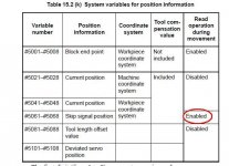
3. A Read Operation of a Skip Signal Position Variable during movement is enabled, as opposed to that of Current Position Variables #5041–#5048. See the attached picture following.
Skip Signal1.JPG

I took this point up with my Fanuc colleagues years ago to confirm my understanding of this variable group. The Skip Signal Position is recorded at the time when the Skip Signal is turned on and remains stored there unchanged until replaced during a subsequent G31 Function execution. This Variable Group is only initialized by cycling the power to the control. Accordingly, the values from this Variable Group can be read at any time after the Skip Function has completed, either by the Skip Signal being turned on, or by the axis move completing without the Skip Signal being turned on.

Sinha said:
So, G31 needs to be commanded twice?
N1 G31 X200. F1000;
G31;
N2 #1=#5061;
N3 #2=#5041;
N4 M0;

G53 and G31 both can be used with the same result?
N1 G31 X200. F1000;
G53;
N2 #1=#5061;
N3 #2=#5041;
N4 M0;
Hello Sinha,
No. In my experience and via instruction by Fanuc, no Buffering Prevention Code is required following a G31 Function for the reasons listed above. However, following is what would happen if a G31 Command were to follow a G31 Command Block.

G31 Z-100.0 F100

Lets say that during the above motion command, a Skip Signal was turned on at Z-85.0. In this case variable #5063 would hold -85000. If a subsequent G31 were to be executed with no axis coordinate specified (no move), if the Skip Signal was still on, any further movement after the previous G31 function would be recorded in #5063. If the Skip Signal is not still on, -100000 (the Block End Point of the previous Block) would be held in #5063.

Regards,

Bill
 
Logically, G31 must prevent buffering; otherwise, it would not serve its intended purpose. Why would an imperfect code be designed.
 
Hi Bill, hi Sinha,
I attach the excerpt from Renishaw's ORIGINAL program (in this case laser tool setter).
"
O9763(REN G31 MOVE)
.
.
.
.
IF[#1EQ3]GOTO4
IF[#1EQ2]GOTO3
G31X#20F[#9*#129]
GOTO5
N3G31Y#20F[#9*#129]
GOTO5
N4G31Z#20F[#9*#129]
N5G53
G4P10
IF[#5GT1]GOTO6
#131=#[5060+#1]-#6(SKIP)
GOTO10
N6#131=#130
#130=#[5060+#1]-#6(TST SKIP)
.
.
.
"
You can clearly see that G53 is used after G31 block, before passing the #506* value to variable #130.

Although, as emphasized several times in the past, I am not taking everything what Renishaw is serving in its "software" for granted, in this case I am sure they know how probes and probing process operate and what is needed to perform this task properly.
 
Maybe Renishaw is being extra cautious.
Has it ever been found that not using G53 immediately after G31 causes buffering issues?
 
Maybe Renishaw is being extra cautious.
Has it ever been found that not using G53 immediately after G31 causes buffering issues?
I don't think Renishaw is writing his routines having in mind being extra cautious. The fenomena exists and programs should be written accordingly.

As to your question, I was facing this problem in almost every Fanuc installation. I am using my own measuring routines, and they, per definition, are all fitted with G53 after each G31 block for Fanuc, or G04 for Meldas / Mazatrol.
Old Fanuc controls (Fanuc 6) do not recognize the G53, but as their look ahead is quite limited, applying several repetitions of G4X0.001 after G31 block does the job.
 
Logically, G31 must prevent buffering; otherwise, it would not serve its intended purpose. Why would an imperfect code be designed.

Hello Sinha,
Exactly.

There are two types of Skip Signals, one being a high-speed skip signal connected directly to the NC; not via the PMC. Delay and error of the ordinary skip signal is 0-2 msec at the NC side (not considering those at the PMC side). The high-speed skip signal input function keeps this value to 0.1 msec or less. The position when the Skip Signal is turned on is held in System Variables 5061 – 5068 and remains intact until another G31 Function is executed, or the power to the control is cycled.

However, if buffering wasn’t prevented, then a subsequent Macro Statement Command Block such as:
#100 = #5061
may be processed before the G31 Function Block is executed. Clearly, Fanuc Engineers were aware of this and made G31 a Buffering Preventing code.

Following are screen shots of a program where a System Variable for Current Position (#5041) that has “Read Operation during Movement” disabled, is used in the Macro A Statement G65 H01 P#100 Q#5041, which is equivalent to Macro B #100 = #5041.

In the following pictures, you can see that no Buffer Preventing Code has been used before the System Variable Read Macro Statement.
Buffering3.JPG Buffering4.JPG
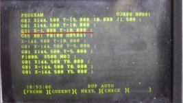
In this case, the Variable was read almost immediately when the X-1.000 Y-10.000 Block was commenced, resulting in 144.3 being registered in Variable #100.

In the following pictures, you can see that G31 is used in conjunction with X-1.000 Y-10.000. Because G31 is a Buffering Preventing Code, and by design will only Skip to the next Block when the Skip Signal is turned On, or the Block reaches its specified End Point without the Skip Signal being turned on, the Macro Statement is not executed until after the G31 X-1.000 Y-10.000 Block has completed.
Buffering1.JPG Buffering2.JPG
In this case, the Variable was read after the G31 X-1.000 Y-10.000 Block was completed, resulting in -1.000 being registered in Variable #100.

Because G31 is a Buffering Preventing Block, following a G31 Function Block with G53 is tantamount to the following Code:
G53
G53
where the second G53 is superfluous.

Regards,

Bill
 
Hi Probe,
I am not questioning what you have observed. But, G31 must prevent buffering. Therefore, if you have faced a buffering problem in some case(s), you may like to report this to Fanuc Japan. Let them analyse this.
They are responsive. I have myself contacted them several times through their website in the past, about 10 years back, in connection with some mistakes in their operator's manual. I always got a reply, in their broken English.
 
Hi sinha,
My answer to your suggestion is going to be a bit philosophical, it deals with responsibilities of field engineer. For years I am implementing probing techniques (hardware and programs) on machines in the field. When problem occurs, it has to be solved on the spot. The customer has no time to let me contact Fanuc, let them digest the problem and then maybe to come with properly performing G31. When I was for the first time facing this buffering problem, I came with the solution of placing G53 block after the G31 block. This simple and effortless action definitely solved the problem, and I am implementing that as default in all my relevant activities.
Apparently, I wasn't the only one who discovered the fact that, contrary to statements in Fanuc manuals, G31 fails to definitely prevent the buffering in Fanuc controls. As mentioned and shown in my previous post, Renishaw themselves recognized that too, and decided to use same G53 technique in their own macros. I am pretty sure that before doing so they contacted Fanuc. And, not trying to be too humble, I am pretty sure that Fanuc treated their complaint more seriously then if that would come from me. And yet the problem still exist.

If definite and simple solution is given to existing problem, the problem does not exist anymore. This is my philosophy. And my obligation as an engineer is to provide such solutions.


Back
Top