What's new
What's new

G41 G42 Tool Nose Radius Compensation Revisited - Again!

Hoppy

Cast Iron
Joined
Feb 21, 2005
Location
Millington, NJ
There are lots of threads on this topic and the more I read, the more confused I get. Let's say, for example, that I touch a right-hand turning/facing tool to the face of a part to establish its Z offset. Let's also say that this tool has a 0.03 nose radius and this (R) value is entered into the control along with a "2" for the tool type (T) value. Now I command a 0.025" face cut towards the axis and, since the tool is to the right of the work, G42 is turned on. Will this cut be 0.025" deep? If the cut is in the opposite direction (+X) and G41 is turned on, what will its depth be?
 
There are lots of threads on this topic and the more I read, the more confused I get. Let's say, for example, that I touch a right-hand turning/facing tool to the face of a part to establish its Z offset. Let's also say that this tool has a 0.03 nose radius and this (R) value is entered into the control along with a "2" for the tool type (T) value. Now I command a 0.025" face cut towards the axis and, since the tool is to the right of the work, G42 is turned on. Will this cut be 0.025" deep? If the cut is in the opposite direction (+X) and G41 is turned on, what will its depth be?

Hi Hoppy,
What is the X+ direction of your machine? At back side of the spindle centre line, going away from the operator, or at the front side of centre, approaching the operator? I ask this question because you appear to be setting the tool as an Imaginary Tool Type 3, but you make reference to Tool Type 2 in your opening Post.

The only time you will over-cut when taking a facing cut perpendicular to the centre line, is if you where to use the wrong Tool Radius Compensation Code (G41/G42) for the operation. When facing from the OD towards the centre, typically G41 would be used, as the tool would have to offset to the Left, relative to the direction the tool is traveling. If the operation is just a facing OP, with the tool withdrawing when it gets to centre line, its generally better to program this OP without Tool Rad Comp. If you were to program the tool to cut to X0.0, then withdraw along the Z axis to be clear of the work, the Z move would prevent the X centre of the tool getting to X Zero and a pip at centre line would be left on the face, the same as if Tool Radius Comp was not used.

Regards,

Bill
 
Last edited:
Always remember that G41/G42 is "Looking in the direction of travel", so you have to put yourself behind the tool as it's moving away from you to determine left/right.
 
Hi Bill,

Mine is a "front turret" machine and +X is therefore moving towards the operator from the spindle center. I used Imaginary Tool Type 2 in my original post to keep the example simple and relevant to the more common "rear turret" machines. As you know, the X component of the Imaginary Tool Types is reversed for the front turret machines and, for example, Type 3 for a rear turret becomes Type 2 for a front turret.

The heart of the issue is this: as long as the correct compensation direction (G41 or G42) is chosen relative to tool motion, shouldn't both examples in my original post produce cuts of the same depth?
 
Hi Bill,

Mine is a "front turret" machine and +X is therefore moving towards the operator from the spindle center. I used Imaginary Tool Type 2 in my original post to keep the example simple and relevant to the more common "rear turret" machines. As you know, the X component of the Imaginary Tool Types is reversed for the front turret machines and, for example, Type 3 for a rear turret becomes Type 2 for a front turret.
Hi Hoppy,
Not so.

I thought your machine must have been a front tool machine by the way you explained the way in which your were trying to apply the Tool Radius Comp, and the typical mistakes made.

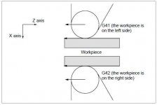
The workpiece position can be changed by setting the coordinate system as shown below. Accordingly, for a tool set as a standard RH OD Turning Tool, the Imaginary Tool Type will be 3 when the coordinate system is set as shown below (X+ towards the operator). The best way to visualize this is by imagining the rear turret and X+ slide being rotated about the centre line of the machine. The RH OD Tools that were upside down at the rear are now upside up, and the X+ slide is at the front of the machine. With this configuration you view the action of the tool from below. What was G42 at the rear is now G42 at the front.

G41_G42_Front XPlus.JPG

The heart of the issue is this: as long as the correct compensation direction (G41 or G42) is chosen relative to tool motion, shouldn't both examples in my original post produce cuts of the same depth?

Yes, both will yield the same result. Both will over-cut by twice the radius of the tool, because you have used the wrong Tool Radius Comp G code in each example. Again, refer to the attached picture above. The easiest way to come to terms with this, when the Coordinate System is as shown in the picture, is to use "the Work is to the Right or Left of the tool" to determine G42 and G41 respectively, rather than use "the tool has to be offset to the Right or Left" to determine G42 and G41 respectively.

Regards,

Bill
 
Hi Bill,

Wow! My old brain is still struggling with this. Would it be correct to say that G41 and G42 are reversed between front and rear turret machines?
 
Hi Bill,

Wow! My old brain is still struggling with this. Would it be correct to say that G41 and G42 are reversed between front and rear turret machines?

Hi Hoppy,
Standing on your feet and viewing the tool path and relationship between Tool and Workpiece in the way G41 and G42 (comp Left and Right respectively) is generally considered, then yes, you could say that they're reversed. However, they actually follow the conventional rules when viewing the tool path from below.

If you wanted to make it more like your general understanding of G41 and G42, then enter the Tool Nose Radius as a negative value. This will reverse the G41 and G42 so you can look at the path of the tool relative to the workpiece and select G41 and G42 as the tool needing to be offset Left and Right respectively. However, if you had a mix of machines where some had the X+ at the rear and some at the front of centre line, its often better to just visualize the tool at the rear and use whatever Tool Rad Comp would be used for the various operations, for the same operations with front mounted tools and X+ towards the operator. In other words, simply imagine the tools and X+ is at the rear of the machine and create the program exactly as you would if the tools and X+ were at the rear.


Regards,

Bill
 
Last edited:
To avoid mistakes trying to visualize "left" and "right", you can also just use rules of thumb:
1) OD turning (on the X+ side of the part), cutting towards the chuck: G42
2) ID turning (inside the part, but on the X+ side of centerline): G41
3) Front facing, cutting from OD toward centerline (moving X-, on Z+ side of part): G41
4) Back facing, cutting from OD toward centerline (moving X-, on Z- side of part): G42

... and of course, if you are cutting any of those same surfaces in the direction opposite what is stated, then swap G41 <-> G42.

These rules should apply equally regardless of whether X+ is towards the front of the machine or towards the back of the machine.

Also remember that cutter radius compensation on a lathe is somewhat different than it is on a mill. On the mill, with no cutter radius compensation, you are commanding the spindle centerline, and you will always overcut (unless you program an offset path to begin with). On the lathe, with no cutter radius compensation, you are commanding the "imaginary tool nose". As long as you are cutting straight diameters or straight faces, with the same sides of the tool as you used to set your X and Z offsets, then you don't need nose radius compensation at all. In general, without cutter radius compensation, the lathe will under-cut (leave too much material behind) on tapers and radii (only).
 
I had some quiet time to spend in the shop yesterday where I could study this and try out a few things. Thanks everyone, I understand it now!
 
I thought I had this down, but now I'm confused again.

Consider these two pieces of code:

T0101
G96 S250 M03
G00 X6.0 Z0.05
G95 G01 Z-1.0 F0.005

T0101
G96 S250 M03
G42 G00 X6.0 Z0.05
G95 G01 Z-1.0 F0.005

T01 is a right hand turning tool and is Tool Type 2 on the offsets. It's got a 0.031 nose radius and this value is also entered into the offsets.

Since this is straight diameter turning towards the chuck on my front turret machine, shouldn't both pieces of code result in a workpiece of the same diameter?
 
You probably need to be using tool nose vector 3.

Nose vector 2 is a tool which points in the X+ and Z- directions: i.e. a boring tool used for ID cuts.

Vector 3 is a tool which points in the X- and Z- directions: i.e. an OD turning and front facing tool.

Nose vectors are defined by which way the tool points with respect to the X and Z axes, not by the way they point as you stand in front of the machine and look at them. Therefore a tool which points in the X- and Z- directions is a vector 3, regardless of whether your turret is in the front or in the back.
 
I thought I had this down, but now I'm confused again.

Consider these two pieces of code:

T0101
G96 S250 M03
G00 X6.0 Z0.05
G95 G01 Z-1.0 F0.005

T0101
G96 S250 M03
G42 G00 X6.0 Z0.05
G95 G01 Z-1.0 F0.005

T01 is a right hand turning tool and is Tool Type 2 on the offsets. It's got a 0.031 nose radius and this value is also entered into the offsets.

Since this is straight diameter turning towards the chuck on my front turret machine, shouldn't both pieces of code result in a workpiece of the same diameter?

Hi Hoppy,
Both would work the same on a straight diameter if the Imaginary Tool Type corresponded with the way in which the tool has been set. If the tool is set as a RH OD Turning Tool, with the leading edge of the tool nose radius in Z and the closest part of the tool nose radius to the machine centre line used in setting, then Imaginary Tool Type 3 should be used; see my Post #5.

Regards,

Bill
 
This old nemesis has got me again! I've got a face grooving tool mounted upside down and am cutting on the -X side of the centerline. My lathe is a "front turret" type. The groove I'm cutting is wider than the tool and I rough it out with two plunges, leaving a small amount of stock for finishing on all surfaces. No nose compensation is used for the roughing. Small chamfers are needed on the groove's corners and the tool has 0.01" radii on both of its corners. I therefore need to program nose radius compensation for the finishing passes. Finishing is in two passes, the first feeding -Z to establish the large diameter of the groove and then +X to create the final depth. Likewise, the second pass establishes the groove's minor diameter and then feeds -X to complete the depth.

I have two problems. First, I'm unsure about the use of G41, G42, and the imaginary tool type here. Do the usual rules switch because of the upside down tool or cutting on the -X side of centerline? The second problem is that regardless of how I apply G41, G42, and the tool type, the depth of the groove is overcut by the amount of the nose radius. All combinations of these produce the same result. Why?
 
Skimmed through this, so don't know if this has been said. TNR comp is not needed in straight facing and turning. Only when contouring (both X & Z moving at the same time). Don't mess your head up using it when it's not needed.
 
First, I'm unsure about the use of G41, G42, and the imaginary tool type here. Do the usual rules switch because of the upside down tool or cutting on the -X side of centerline? The second problem is that regardless of how I apply G41, G42, and the tool type, the depth of the groove is overcut by the amount of the nose radius. All combinations of these produce the same result. Why?

Answer to your first question = no
Think of driving a car with the driver side door rubbing against a wall(left side for non Europeans). The car is the tool the wall is the part. This would be a G42... used for typical OD turning, or any case where the part is to the LEFT of the tool.
If you're driving and the passenger side door is rubbing a wall, this would be G41.. used for typical facing and ID boring where the part is to the RIGHT of the tool.

If it's a face groove and you need to radius the smaller dia of the groove, this would be a G42 IF you're cutting from the face and go in Z minus direction.

Cutting a radius on the larger diameter of the face groove this would be a G41.

Make sure you have the tool tip number set correctly.. 1 thru 8, and you have the correct insert radius set in the tool offset page or else you will get funky movements and scrap the part.

I hope I didn't confuse you with my analogy :willy_nilly:
 
Doesn't answer your question but a lot of times on grooves I just figure comp into the tool path. And use two offsets to hold the width.

Brent
 
Answer to your first question = no
Think of driving a car with the driver side door rubbing against a wall(left side for non Europeans). The car is the tool the wall is the part. This would be a G42... used for typical OD turning, or any case where the part is to the LEFT of the tool.
If you're driving and the passenger side door is rubbing a wall, this would be G41.. used for typical facing and ID boring where the part is to the RIGHT of the tool.

If it's a face groove and you need to radius the smaller dia of the groove, this would be a G42 IF you're cutting from the face and go in Z minus direction.

Cutting a radius on the larger diameter of the face groove this would be a G41.

Make sure you have the tool tip number set correctly.. 1 thru 8, and you have the correct insert radius set in the tool offset page or else you will get funky movements and scrap the part.

I hope I didn't confuse you with my analogy :willy_nilly:

Hello Mtndew,
Hoppy doesn't actually say if X+ direction is towards the front or the rear with his front mounted turret. If the tools are mounted at the front, between the operator and the work, and the X+ direction is towards the front (towards the operator) then G41/42 will be contra to your explanation.

If a convex radius is being cut from the face to the OD of the workpiece with a front mounted tools and X+ towards the front, G42 TRC will be used, exactly the same as when cutting a convex radius from face to OD of the workpiece with a machine having rear mounted tools and X+ towards the rear.

Accordingly, if a convex radius is cut on the Large D of a face groove, from face to ID of groove, with the tool mounted so that it is cutting the Large D on the minus side of centre line, then the direction of the tool path will be the same as the convex radius being cut from face to OD of workpiece with tool mounted at the front of the machine and on the X+ side of centre line.

Front Mounted Turret1.JPG

The tool being upside down is irrelevant in determining which TRC G code to use. As long as the tool path direction is the same with the tool Up Side Down or Up Side Up, the TRC G Code will be the same for both.

Regards,

Bill
 
Last edited:


Back
Top