What's new
What's new

Getting acquainted with the Fanuc 5T- How to navigate control?

Garwood

Diamond
Joined
Oct 10, 2009
Location
Oregon
I have a 1980 Mazak M4 lathe with a 5T control. I purchased the machine without a specific need for it and it has not been used for actual programmed machining, just used it quite a bit in handwheel/jog modes over the past year. I now have actual work for this machine, but finding the control with it's one line display is much harder to navigate than I expected. There's a full set of manuals for this machine, but the procedures outlined in the operations manual are unclear to me or just not possible (the control lacks buttons or is layed out differently than the manuals present it to be).

The only CNC experience I have is with the 6M Fanuc control on my mill. I have not programmed a CNC lathe before. The Fanuc 6 is a hell of a lot simpler with a full screen.

Right now I'm struggling with-
How do I enter code into this 5T in MDI? If I want to hand key in a simple program how do I do it? There's no "O" for a program number? Even simpler yet- How do I do anything with MDI like enter code manually to change a tool or start/stop the spindle?

I was expecting to find work shift values in the control like G54,G55 as my mill uses, but the control doesn't seem to have this? I've read through old threads on this site and others about the 5T using G50 followed by X and Z values in a line of code. How do I use the G50 code/values?

How are tool offsets entered?

There has to be someone who remembers how to use a 5T!
 
I have a 6t on a wasino lathe. I'm not sure how close it is to a 5t, but i would assume the differences aren't huge. Im no lathe expert, but i could prbably help you get started with it. If i can be of any help, pm me, and i'll give you my number.
 
Alloy Mcgraw- PM sent, thank you for the offer!

I've been reading everything I can find on old lathes that use G50. I'm starting to understand why I've struggled with this so much coming from a mill that uses G54,G55, etc geometry offsets. What I gather so far is that my 5T isn't capable of keeping track of geometry offsets in the control. It completely lacks this feature and so did all the other lathes built in 1980 so when the manual describes using G50 I would know that every tool requires it's own G50 command in the program if I was reading the manual 30 years ago before geometry offsets were used in the control.

In regards to the use of G50, the part that's still fuzzy for me is how the control interprets it. Do I program using G50 by entering a line such as "G50 X0 Z0" with the machine in the zero return position then program all the moves based on the machine's zero return position as program zero? Or do I use G50 in such a way that it tells the control where program zero is in relation to where the machine is at at that exact time, for instance, with both axis in the zero return position I use a line such as "G50X-20000Z-250000" and that tells the control that program zero, the zero point for the WCS of the part to be made is 2" closer to the chuck in X and 25" closer to the chuck in Z?

To program this way I would touch off all the tools, use the relative display to measure their distances from wherever my part zero is going to be (end of part Z and center of part X) and the zero return position. I write down the offset amounts for each tool then use those distances in the program by entering a G28 zero return, then a toolchange, then the proper offset amount for that tool using "G50 X-xxxxxZ-xxxxxx"?

Clear as mud right? I'm sure by next week I'll feel like an idiot for even asking such basic questions. It seems like programming/learning a control becomes very simple once you grasp the basic ideas.

Thanks for any help!
 
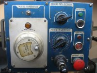
Here are pictures of the control and pendant on the Mazak.
mazak 001.jpgmazak 002.jpg

The upper portion of the display has a row of LED's under letters with two right and left arrow keys to select the letter you want. Pressing the arrow keys moves the lit LED.

The lower portion of the display has numbers I can key in on the left and a 2 digit 01-99 display I can toggle through with up/down buttons . I can move the lit LED around to different letters and I can key numbers into the display, but I don't understand how exactly this works to enter a line of code. I can key numbers in and press enter, alter or EOB and the numbers just disappear.
 
I had the thrill of programming a 5T back in 1979. The one line LED display can be toggled to X, Z F etc, but only one line at a time. This system makes even the most rudimentry CRT a relative joy to use. There is no G54. There are no program numbers. From what I can remember (it's been a while!) there is a "main" and a "sub" program; that's all!
I was never able to actually run the machine without the operator ("Mr Elbows"; I couldn't even enter data on the control because that was "His job" even though I was the programmer) but I believe that this control could be programmed like modern units where the corner of the turret can be used as the coordinate point with tools offset in a more or less "modern" fashion.
If I lived nearby, I'd be happy to drop by but.....
 
You may not believe this, but machines with the 5T are still used a lot and even sold once in a while.
I worked with fanuc way back teaching programming on this and there is quite a bit on on of my Fanuc DVDs.
Look on www.doccnc.com
Call me with questions if you want 614-888-8466
Heinz.
 
Here are pictures of the control and pendant on the Mazak.
View attachment 50605View attachment 50606

The upper portion of the display has a row of LED's under letters with two right and left arrow keys to select the letter you want. Pressing the arrow keys moves the lit LED.

The lower portion of the display has numbers I can key in on the left and a 2 digit 01-99 display I can toggle through with up/down buttons . I can move the lit LED around to different letters and I can key numbers into the display, but I don't understand how exactly this works to enter a line of code. I can key numbers in and press enter, alter or EOB and the numbers just disappear.
Hi Garwood,
A program can be entered into the 5T control in a couple of ways, either via
1. EDIT Mode and the Addresses available through the 7 segment LED display in conjunction with the Edit buttons above the Position Readout display in your attached picture.
2. The Tape Reader and a paper or mylar tape, again using EDIT Mode.

The above two methods registers a program into memory. MEMORY Mode is used during Auto operation of the machine. The machine can also be controlled via the Tape directly. In this case TAPE Mode is selected. Whatever method is used to register the program, its a tedious exercise.

Once the program is registered in memory, to check the content is equally tedious as the registering procedure. When the program is running, you are not able to view the complete block of the current executing block. If you wanted to see what X value is modal, you do so by selecting the X address via the Left/Right arrow to illuminate the LED below the Address Character "X". The same procedure applies for all other Addresses used in the program.

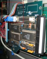
I fit Behind Tape Readers (BTR) to many of these old controls and supply software that rejuvenates and makes the control very user friendly. In the attached picture on the left, a BTR is shown installed in the control. These devices are simple to install, requiring only a screw driver to do so. In the case of the pictured installation, I dismantles a PC and mounted the components where I could inside the control enclosure, there is plenty of room. The Rainbow cable shown in the Red rectangle, connects directly to the Com port of the PC's mother board mounted out of picture, but just below the BRT. The PC was then connected via a Local Area Network to the computer where programs were prepared and stored. A monitor and Keyboard, mounted on a pull out tray, were installed conveniently for the operator. This installation was able to retrieve programs stored externally, via the LAN, via a USB port and a Memory Stick, or programs could be created at the machine via the CAM software installed on the inbuilt PC attached to the BTR.

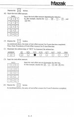
The attached picture on the Right shows a screen shot of the Custom software I wrote for 5T/BTR applications. The routine is a modification of my Editor/Comms package to allow the operator to view the Current and Pending program blocks whilst the machine is operating via DNC. Although the software can be used to Upload programs into the control's memory, DNC is the best method to use with this software as the program is viewable in real time as its executing, with the cursor highlighting the Pending Program Block. Restarting the program from any point is easier than doing so with a late model Fanuc control.

Geometry Offset Programming is not available with the 5T control. The Coordinate System is established via G50 Coordinate Set Command.

Unless you have either a digital or hard copy of the control's parameters, make one now. The Fanuc manual only lists parameters from #003 to #019. All other parameters are MTB related. There are two battery packs attached to the main board of the 5T. One is in the form of three SR44's joined in Series to total 4.5vdc connected centre top of the mother board. This battery pack is to retain the parameter memory. As is the case with all Fanuc Control batteries, these should be replaced annually. When I have to replace these batteries, I do so with a carrier that takes "AA" batteries. The other set attaches to the centre bottom of the mother board and retains the program memory. Always replace the batteries with the control powered up. Disconnect the batteries with the power turned off will result in the loss of the Parameter and Program memory.

I can advise you regarding the exact keystroke by keystroke procedure to register and run a program, but my better advice would be to tell you to fit a BRT and make a really usable control out of what you have. There are quite a few manufacturers of BTR's. The one I use and have found to be most reliable is made here in Australia. I can supply further information regarding same should you decide to got that way.

Regards,

Bill

BTR3.JPG ; DNC1.jpg
 
Last edited:
The best advice I can give is to number all your program lines. I ran a 3T that didn't even show a whole line. By numbering every line N1, N2, N3 etc, it made searching pretty easy.
 
I just remembered one thing that you had to do to create a program.
With the memory empty, you have to enter:
001
002
003
004
etc until you have "enough" block numbers for your program.
You then go back and enter the G codes, X's and Z's to finish creating your program.
This is one procedure that I remember as being different from any control with a monitor.


I've never seen nor heard of that that with either a 5T or the Mill equivalent 3000C control. Each block of the program is entered one address word at a time and terminated with and EOB. With the BTR and software described in Post #7 the program can be registered in an empty memory using no leading blank lines or numbered lines whatsoever. When using a BTR, the control functions exactly how it does when reading from a Tape and the format has to be exactly how it would be if entering a program via the key pad.

Garwood,
It appears from your Post #3 that you realize the 5T can't tolerate a period in the coordinate address word, and that all trailing Zeros must be included. The Software briefly described in Post #7 allows for a program to be created with periods, and therefore easier to read than without the period Format, but when the program is either uploaded to the control, or sent via DNC, the code is formatted correctly for use by the control.

Regards,

Bill
 
The procedure I mentioned (001,002,003) is required on both the 3000C and 5T when entering a program at the keypad (only).
If you have loaded a program by punched tape, this is not required; the control simply reads the block numbers as you would expect.
One other thing I remember was that a program with an "illegal" G or M code would simply stop reading when inputting a program from tape; a major PITA. You would have to remove the offending code from the tape and then try to reload it. (In my case, we had two machining centers with 3000C controls. One used G28 while the other did not. That G28 would stop program loading instantly)
 
Here is a sample program, turn and face a 2" diameter part made from 1018 steel:
From distant mmemory, mine
N1 G50 X100000 Z60000 S1500* (All dimensions without decimal points, learn to set G50 dimensions)
N2 T0100*
N3 S400 M3*(You may or may not have G96, so all s values are in RPM)
N4 G0 X21000 Z0 T0101 M8*
N5 G1 X-600 F80*
N6 G0 X20000 Z1000*
N7 G1 Z-15000 F120*
N8 G0 X10000 Z60000 T0100 M9*
N9 M30*
This is as close as I can come, good luck.
By the way, the input description earlier was excellent.
Heinz.
 
A couple of details I forgot:
There is no noseradius comp on the 5T, you have to learn to calculate it.
This and also the control input is on my DVD called "Supplemental Math"
The programming is on the DVD called "Fanuc 5T'
Website is: www.doccnc.com
Good luck: Heinz.
 
A couple of details I forgot:
There is no noseradius comp on the 5T, you have to learn to calculate it.
This and also the control input is on my DVD called "Supplemental Math"
The programming is on the DVD called "Fanuc 5T'
Website is: Fanuc CNC programming training. Learn CNC for Fanuc, Yasnac, Mitsubishi CNC controls, CNC Machining Videos and DVD's, CNC programming training, CNC education,and CNC consulting.
Good luck: Heinz.

Not so Heinz. Most assuredly, TNR compensation and Cutter Radius Compensation is available on the 5T and 3000c control respectively.

With a machining centre, cutter radius compensation is essential, as its the means by which the size of features is regulated when using end mill type cutters, cutting with their circumference. I don't favor using TNR compensation with a lathe control, the reasons being:
1. TNR Comp its ignored in the Multi Repetitive cycles. Accordingly, if one of these roughing cycles are to be used, you would need to calculate the true position of the tool taking into account of the TNR for the profile description.

2. Unlike a Mill control, in the overwhelming majority of cases the size of the workpiece is regulated by the Wear Offset

3. When machining towards the chuck G42 would be active (tool right of the profile), when returning the tool to the start position, tool right of the profile will be into the workpiece if one is not observant and ensure that G42 is replaced by G41 or G40 on every direction reversal, or ensure that the tool is retracted more than the Tool Nose Radius before reversing the traverse direction. Significant if say a tool with a R6.0 round button insert is used.

The data used in TNR compensation, that is, the TNR and the Tool Type number, is stored in the Offset Registry Numbers +30 of the offsets used to store the Wear Offsets. You will see in the attached picture, OFR and OFT to the right of OFX and OFZ in the address bar. The LED below these two addresses are to be illuminated when inputting the TNR data.

Also Heinz, you can't drop the leading Zeros in any of the Address Words as shown in your Post #12. For example G0, G1, G2, G3, G4, M0, M1, etc instead of G00, G01, G02, G03, G04, M00, M01, etc is not allowed.

scan0056.jpg

706jim said:
The procedure I mentioned (001,002,003) is required on both the 3000C and 5T when entering a program at the keypad (only).

We'll have to agree to disagree on this point. I look after a number of these old controls for clients and this is clearly not the case with any of their machines. For starters, how do you input numerals only (001,002,003)? The Insert process with this model control is to first select an Address character using the Address Left/Right buttons. The selection process is to merely illuminate the LED corresponding to an Address; no Insert or Input is required to select the Address. A numeric value is then entered via the Keypad before pressing Insert to register the Address character corresponding to the illuminated LED, and the numeric value. As the selection of the address is by way of illuminating the Address character LED only, there is always some Address selected, unless the illuminated LED is in the Offset/DNG/PRM area, and then the program memory area is shut out. Accordingly, your 001,002,003 etc, will be registered along with an Address character.

Regards,

Bill
 
Last edited:
To program this way I would touch off all the tools, use the relative display to measure their distances from wherever my part zero is going to be (end of part Z and center of part X) and the zero return position. I write down the offset amounts for each tool then use those distances in the program by entering a G28 zero return, then a toolchange, then the proper offset amount for that tool using "G50 X-xxxxxZ-xxxxxx"?

Hi Garwood,
You will have to test this on your machine, but on all machines equipped with 5T controls I've played with, if the machine's slides are at the Reference Return position when G28 U0 W0 is executed, the slides will move in the direction of the reference position relative to the chuck (normally a positive direction), notwithstanding that the slides are already at Home, and obviously hit the Over Travel switches. Using G28 U0 W0 when the slides are not at Reference Return works normally.

Regards,

Bill
 
I truly appreciate the time all of you have taken to help me. I will try keying in some code in the machine again this evening following the advice given here and see what happens.

On a positive note the lathe does have a BTR from Advance Digital Research installed. I'm going to pick up the proper serial cable to connect the BTR and new batteries for the control while I'm out today.

Thanks!
 
Garwood- I tried calling you the other night, but got no answer. After looking at the pics of the control, its quit different from the 6t i have. But as far as the way the G50s and such work, if you run into any trouble, feel free to call me at the number i sent on the PM. Best of luck.
 
After looking at the pics of the control, its quit different from the 6t i have. But as far as the way the G50s and such work, if you run into any trouble, feel free to call me at the number i sent on the PM. Best of luck.

As far as the functionality goes, the Series 5 and 6 are the same. Some of the very early 6TA controls actually had the same 7 segment Address display (no CTR screen) as the 5T and it was hard to tell the two controls apart. The biggest difference between the Series 5 and Series 6 control is that the Series 6 tolerates periods (decimal points) in the program address words.

Garwood,
The most important thing to be aware of when using G50 to set the coordinate system is that each tool must be located at same point every time the G50 command is executed. Accordingly, the tool change position needs to be at an easily repeatable position, like Reference Return for example.

Mazak M4 and M5 turning centres came in quite a few length configurations; generally 1.5M plus. To accommodate short work, there is a moveable Z Zero return dog on a bar calibrated in 10mm increments, tucked under the front of the bed-way. This is used to reposition the Z axis Reference Return position, and therefore eliminate the need to go way up the bed-way to execute a Z Reference Return.

Unlike a control using Geometry Offset Programming, where, if the program is aborted due to a failed insert or for whatever reason, the program can be repeated with the Tool parked in any safe position, a machine using G50 to set the coordinate system must have the tool start from exactly the same point before the G50 command is executed. As mentioned earlier, this position is frequently the X,Z Reference Return location, as its an easily locatable position. If a production job is being run, where you may wish to limit the amount of Rapid Travers move from Tool Change position to Workpiece, the following can be used throughout the program in the event that the program has to be aborted and restarted:
(Metric Example)
N1 G00 G21 G40
/G28 U0 W0
/G00 U-150000 W-200000
G50 X250000 Z150000 (OR WHATEVER IT MAY BE)
G50 T0100 S2500
G96 S200 M03
G00 X100000 Z10000 T0101 M08
---------
---------
---------
---------
G00 X250000 Z150000 T0100 M09
M01
(NEXT TOOL)
/N2 G28 U0 W0
/G00 U-150000 W-200000
G50 X220000 Z100000 (OR WHATEVER IT MAY BE)
G50 T0200 S2500
G96 S200 M03
G00 X100000 Z10000 T0202 M08
---------
---------
---------
---------
G00 X220000 Z100000 T0200 M09
M01

and so on.

Always select a tool without an offset, for example T0100 and not T0101. Then apply the offset on the next move command. To call the tool with T0101 will result in the carriage moving the Tool Offset amount during the tool index. If the carriage is parked at the Reference Return position and the Offset amount is considerable, the slide can move into Over-travel. Also, its important that the Tool Offset is cancelled as the tool is returned to the Tool Change position. Not observing this precaution will result is a gradual shift of the Tool Change position and ruination of the workpiece.

By having the following with a block delete,
/N2 G28 U0 W0
/G00 U-150000 W-200000
anytime a Tool Change position other than the Reference Return position needs to be found, it can easily be done so by turning the Block Delete switch off and allowing the first two blocks to execute. Once back at the Tool Change position, the Block Delete switch is turned back on.

There are many ways to determine the G50 value for each tool, following is one that's fairly reliable.

1. Reference Return both axes.
2. Zero both the X and Z position display by pressing the corresponding buttons to the right of each display.
3. Manually index the required too into position.
4. Manually start the spindle and adjust RPM to an acceptable level to take a cut on a workpiece mounted in whatever the work-holding device is.
5. Move the tool to the workpiece and take a light cut on the OD.
6. Clear the tool of the workpiece in Z only without moving the tool in X.
7. Stop the spindle, measure the workpiece and note.
8. The values shown in the position display is the distance the tool tip is from the Reference Return position, displayed as a negative value. Add to the X value, the diameter measurement of the workpiece as a negative value. The positive of the result is the G50 for X when the X slide is at the X Reference Return position.
9. Start the spindle and take a light cut on the end of the workpiece.
10. Clear the tool of the workpiece in X only and without moving the tool in Z. Measure from the end of the machined workpiece to where Z Zero is for this workpiece.
11. If there is, say, 1.05mm between the current machined end and Z Zero, add as a minus value 1.05mm to the current negative value being shown on the Z position display. The positive of the result is the G50 for Z when the Z slide is at the Z Reference Return position.
12. If the tool change X,Z position is to be set distances away from the Reference Return positions, subtract these distances from the results gained in 8 an 11 above to obtain the X, Z G50's for this location.
13. Repeat the above for all other tools to be set.
14. As the position display was initially Zeroed at the Reference Return position, the tool turret does not require to be Homed between the setting of each tool. Just move the carriage to a safe Tool Change position and select the next tool.
15. The above example is for an OD tool. The same procedure is followed to set an ID tool, except, obviously, a bore is cut and measured to gain the X G50.

Its seldom that the G50's will be whole, round numbers. For this reason, I advise my clients to use the Integer component of the result gained in 8, 11, or 12, and use the decimal component as the Tool Offset. This works out well when the control is used in the Metric Mode, as the decimal component will always be quite small, less than 0.040". When using the Imperial system, I round down to the closest 0.5" increment and use the remainder as the Tool Offset. This method will consistently result in Mono Direction offsets and round, clean numbers as G50's in the program.

Its likely that your lathe has a rear turret for Internal Tools. This being the case, the X G50's will be all Negative values for the back turret tools. When programming Circular Interpolation moves for the back turret, the direction of G02/G03, when viewed from above, is reversed. For example, a clockwise move will be G03.

Single blocks of program data can be executed via MDI. For example, to move the X, Z slides incrementally -100.00 and -150.00 respectively, proceed as follows:
1. Select MDI Mode
2. Via the Address arrows, select G Address
3. Enter 00 via the Keypad and press the Input button
4. Select Address U. Note, if you press and hold down the Right Address arrow, the LED cursor will move continuously. To move the Address LED to the left, the Left Address arrow has to be pressed and released between single Address LED moves.
5. Enter -100000 and press Input
6. Select Address W
7. Enter -150000 and press Input
8. Depending on parameter settings, pressing the Start button near the Keypad will execute the block just entered. If the block does not execute when the Start button is pressed, press the Cycle Start button. Cycle Start will execute the block in MDI irrespective of the parameter setting.

I hope the above is clear and helpful to you.

Regards,

Bill
 
Last edited:
Bill,
I'm at a loss for words to describe how helpful what you took the time to type out has been for me. I am very grateful and a little astonished that you are so familiar with my exact machine. You answered every question I had and a couple I wasn't aware of yet. My M4 is the middle size model with 60" centers and a 6 position rear turret. I was cautioned about rear turret use, but nobody mentioned the G02/G03 reversal. Thank you!

Hi Garwood,
I look after all manner of machines for clients; accordingly, I have a fair understanding of many machines.

One thing I didn't mention with regards to the rear turret, and that is, you need to be very aware of its index position when using the front turret. Tool interference from the rear turret is a real issue with your machine's configuration when the front turret is being used. Accordingly, you should formulate a safety index block for the rear turret to be included in your program every time a front turret tool is commanded. This should be included every time a front tool is indexed, irrespective of whether a rear turret tool has been used or not. If the rear turret is already in the correct index position, no time penalty whatsoever is incurred by commanding that tool again. By including it every time, it gets you into a habit, and if it isn't in the correct position, then maybe this safety block will have allowed you to dodge a bullet. For example, you might have something like the following:

N1 G00 G21 G40
/G28 U0 W0
/G00 U-150000 W-200000
G00 T2200 (SAFE TOOL INDEX FOR REAR TURRET)
G50 X250000 Z150000 (OR WHATEVER IT MAY BE)
G50 T0100 S2500
G96 S200 M03
G00 X100000 Z10000 T0101 M08
---------
---------
---------
---------
G00 X250000 Z150000 T0100 M09
M01
(NEXT TOOL)
/N2 G28 U0 W0
/G00 U-150000 W-200000
G00 T2200 (SAFE TOOL INDEX FOR REAR TURRET)
G50 X220000 Z100000 (OR WHATEVER IT MAY BE)
G50 T0200 S2500
G96 S200 M03
G00 X100000 Z10000 T0202 M08
---------
---------
---------
---------
G00 X220000 Z100000 T0200 M09
M01

Its a distinct bonus that your machine has a BTR. This device makes the machine that you have many times more useable than what it normally would be.

If you have any other questions regarding the programming and operation of your machine, I'm sure I'll be able to answer them for you.

Regards,

Bill
 
Last edited:


Back
Top