kazlx
Hot Rolled
- Joined
- Nov 22, 2010
- Location
- Tustin, CA
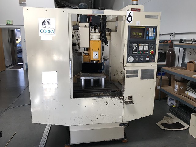
Long story short, I have a smaller drill/tap/mill machine that crashed the toolchanger (not of my doing). The machine is an '89 and it was a previous semi-hidden repair. After digging into it more, I see why they did what they did and was able to repair the damage and hopefully keep it from happening again. The tool changer is controlled all mechanically. I finished the repair, re-assembled the machine and have it working semi-reliably. The problem is, every 10-12 tool changes, it drops the tools, which makes me thing the arm is not 'clocked' or set correctly.
I'm trying to figure out a good method to identify and set where the arm should be. I was an idiot and didn't mark it when it came apart, thinking there would be a keyway or something to basically re-align it. After seeing how it goes together, I'm stuck. The mechanicals to the tool changer are in the gear box, with the shaft that sticks out down between the spindle and the tool changer. The arm and 'claws' use a clamping system of a stack of tapered split wedge type sleeves that tighten down to pinch the arm to the shaft. After it's tightened down, you basically have to loosed the whole thing and break the tapers, re-set everything and re-install to put it back. There's no way I've found to make small adjustments and test.
So I'm trying to figure out a good method to figure out where the arm should be initially.
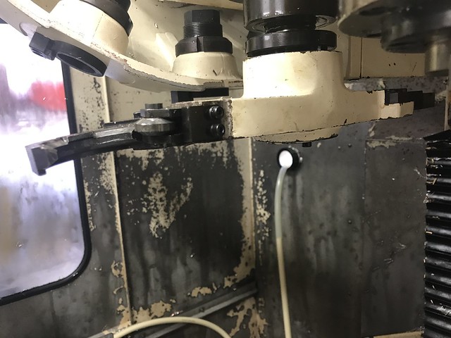
This was essentially the damage. It bent the pocket the claw was in. I was able to straighten and re-weld and get everything buttoned up. I'm 90% sure my problem is 'rotational clocking' of the tool arm. Because when it does drop tools, it always drops both and the other 90% of the time it works fine.
Pic. The tool arm is small and short. The tools are BT30. There are 6 bolts that go though the bottom and into the black oxide ring directly above the arm. Tightening those clamps the tapered split rings together and clamps the arm on the shaft. \
Any help is appreciated. I just want to get this back up and running. Side note, there is no manual tool change button that I can find on this machine. I've looked all over. Previous owner said the same. Didn't think much of it until the tool changer crashed, otherwise I could just run it that way.
My other, other backup plan is to possibly figure out how to change tools manually, which I could probably do with removing the arm and the correct code, but I would need to figure out how to make sure the machine know which tool is in the spindle and keeps the offsets correct. Open to suggestions for the possibility of that as way.
I'm basically open to any options or suggestions. It's what I got, It's paid for, just trying to get it making parts again.
I'm trying to figure out a good method to identify and set where the arm should be. I was an idiot and didn't mark it when it came apart, thinking there would be a keyway or something to basically re-align it. After seeing how it goes together, I'm stuck. The mechanicals to the tool changer are in the gear box, with the shaft that sticks out down between the spindle and the tool changer. The arm and 'claws' use a clamping system of a stack of tapered split wedge type sleeves that tighten down to pinch the arm to the shaft. After it's tightened down, you basically have to loosed the whole thing and break the tapers, re-set everything and re-install to put it back. There's no way I've found to make small adjustments and test.
So I'm trying to figure out a good method to figure out where the arm should be initially.
This was essentially the damage. It bent the pocket the claw was in. I was able to straighten and re-weld and get everything buttoned up. I'm 90% sure my problem is 'rotational clocking' of the tool arm. Because when it does drop tools, it always drops both and the other 90% of the time it works fine.
Pic. The tool arm is small and short. The tools are BT30. There are 6 bolts that go though the bottom and into the black oxide ring directly above the arm. Tightening those clamps the tapered split rings together and clamps the arm on the shaft. \
Any help is appreciated. I just want to get this back up and running. Side note, there is no manual tool change button that I can find on this machine. I've looked all over. Previous owner said the same. Didn't think much of it until the tool changer crashed, otherwise I could just run it that way.
My other, other backup plan is to possibly figure out how to change tools manually, which I could probably do with removing the arm and the correct code, but I would need to figure out how to make sure the machine know which tool is in the spindle and keeps the offsets correct. Open to suggestions for the possibility of that as way.
I'm basically open to any options or suggestions. It's what I got, It's paid for, just trying to get it making parts again.