Triam
Plastic
- Joined
- Jun 13, 2013
- Location
- Salt Lake, Utah
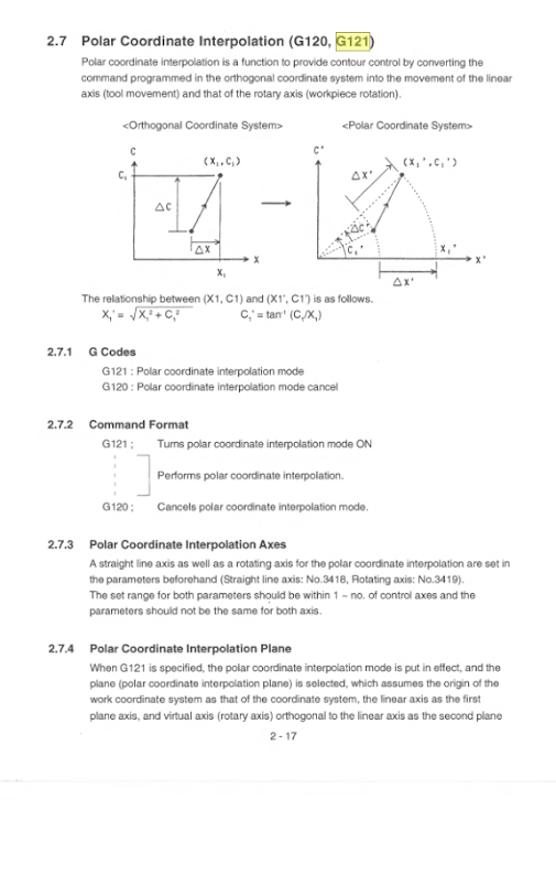
So we've got a mill turn system at work that I just took over. I'm trying to figure out all its bells and whistles. It didn't have the polar coordinate feature activated until I talked with a tech that did it for me. It'll interpolate correctly in that it will now feed inches/min instead of degrees/min. The problem is that it'll maybe do a few interpolations but as it goes it will move further and further away from the chuck. I assume it's moving in incremental mode, but once I have G121 (polar interpolation) activated it'll throw an error if I put G90 in the code. I've tried quite a few iterations of this, but here's the sample code:
%
O1112 ( .TXT )
(Hitachi_Seiki_Super_HiCell_250_Post)
G170
G28 WB0
G30 U0.
G30 V0.
G30 W0.
M1
N1 T021000
T991500
G40 G80 G17 G54 M43
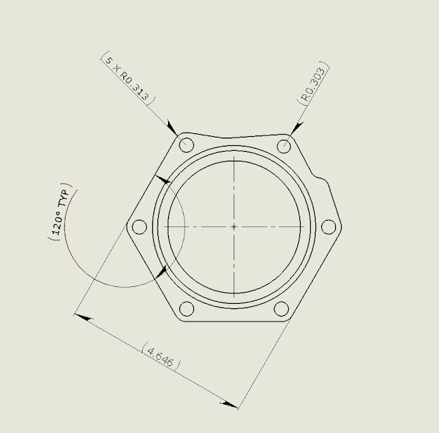
(---OP1 F-CONTOUR---)
G97 G98 S1000 M13
M8
G121
G0 X5.4162 Z0.4 C-4.6374 F50.
G0 Z0.0393
G1 Z-0.001 F1.32
G42 X5.4154 C-4.6338 F10.
C-55.3662
G3 X2.32 C2.4467 R0.4375
G1 C-115.3662
G3 X-3.0778 C2.2279 R0.4375
G1 C-175.3662
G3 X-5.3983 C-0.2183 R0.4375
G1 C-235.2271
G3 X-2.1936 C-2.4382 R0.4375
G1 X4.646 C-263.3303
G2 X-0.37 C-2.3036 R0.375
G1 X5.358 C-296.3943
G3 X3.2 C-2.1714 R0.428
G1 X4.888 C-325.1599
G2 X4.1817 C-1.3319 R0.125
G1 X5.0508 C-328.5232
G3 X4.8663 C-1.0676 R0.375
G1 X5.4788 C-357.1712
G3 X5.3978 C0.2188 R0.4375
G40G1 X5.4162 C-364.6374
G0 Z0.4 F50.
M15
G120
M9
G30 U0. V0.
G30 W0.
M41
M30
%
I've tried changing X to U and the same thing happens. I've also tried either having no X words, typing in X0, and putting U0 in the code and it still moves away from the spindle. Can anyone help me figure out why this is happening?
%
O1112 ( .TXT )
(Hitachi_Seiki_Super_HiCell_250_Post)
G170
G28 WB0
G30 U0.
G30 V0.
G30 W0.
M1
N1 T021000
T991500
G40 G80 G17 G54 M43
(---OP1 F-CONTOUR---)
G97 G98 S1000 M13
M8
G121
G0 X5.4162 Z0.4 C-4.6374 F50.
G0 Z0.0393
G1 Z-0.001 F1.32
G42 X5.4154 C-4.6338 F10.
C-55.3662
G3 X2.32 C2.4467 R0.4375
G1 C-115.3662
G3 X-3.0778 C2.2279 R0.4375
G1 C-175.3662
G3 X-5.3983 C-0.2183 R0.4375
G1 C-235.2271
G3 X-2.1936 C-2.4382 R0.4375
G1 X4.646 C-263.3303
G2 X-0.37 C-2.3036 R0.375
G1 X5.358 C-296.3943
G3 X3.2 C-2.1714 R0.428
G1 X4.888 C-325.1599
G2 X4.1817 C-1.3319 R0.125
G1 X5.0508 C-328.5232
G3 X4.8663 C-1.0676 R0.375
G1 X5.4788 C-357.1712
G3 X5.3978 C0.2188 R0.4375
G40G1 X5.4162 C-364.6374
G0 Z0.4 F50.
M15
G120
M9
G30 U0. V0.
G30 W0.
M41
M30
%
I've tried changing X to U and the same thing happens. I've also tried either having no X words, typing in X0, and putting U0 in the code and it still moves away from the spindle. Can anyone help me figure out why this is happening?