What's new
What's new

ID thread milling flank angle error?

MattiJ

Titanium
Joined
May 31, 2017
Something I have been wondering for a while:
If internal threads are thread milled the cutter need to have modified flank angle or the resulting flank angle has some error. But how much?

And secondly: are the thread milling cutters grind for some certain pitch or helix angle?
In theory you get different flank angle if you use same cutter for M6 x1mm internal thread compared to if you use it for M20x1 thread?
What's the acceptable range?


The only time you'll run into issues is when you use a threading tool that is too big for the bore.
For instance, a large, course thread-mill cutter will have a larger, thicker insert.
The extra thickness of the insert will cause it to drag on the back side, theoretically.

Each manufacturer has different published specs for the range of threads that can be cut with each tool.
That's because there are at least three factors that need to be accounted for: Thickness of insert, cutter radius, cutter relief angles.

Check with the tool maker. Going up in hole diameter won't cause problems, but going down too small might.

Outside threads are no problem. The two arcs curve away so fast that extra clearance is created.
 
Something I have been wondering for a while:
If internal threads are thread milled the cutter need to have modified flank angle or the resulting flank angle has some error. But how much?

And secondly: are the thread milling cutters grind for some certain pitch or helix angle?
In theory you get different flank angle if you use same cutter for M6 x1mm internal thread compared to if you use it for M20x1 thread?
What's the acceptable range?
I don't think the smaller ones are corrected at all. The roll forms for thread grinding are not. At a certain point, for thread grinding and milling, they tip the wheel to correct the angle. Threading in a lathe is usually not corrected for smaller pitches. Sandvik threading tools have different angled seats available for different pitches but not sure if anyone uses them ? For wormgears there are different calculations depending on whether the worm was milled/ground or turned but again, not many people bother with that for finer pitches.

In smaller pitches, i think people just fake it.
 
Sandvik threading tools have different angled seats available for different pitches but not sure if anyone uses them ?
I thought that angled seats on single point tools have more to do with providing clearance angles than getting desired flank angles or correct thread profile.
 
Something I have been wondering for a while:
If internal threads are thread milled the cutter need to have modified flank angle or the resulting flank angle has some error. But how much?

And secondly: are the thread milling cutters grind for some certain pitch or helix angle?
In theory you get different flank angle if you use same cutter for M6 x1mm internal thread compared to if you use it for M20x1 thread?
What's the acceptable range?

This is not usually an issue with 55+ degree threads as the thread form angle is sufficient to not interfere with the trailing flank in most normal cases - small tool, small helix angle, large form angle.

It becomes a real issue with "squarer" thread forms like TR and ACME.
 
I thought that angled seats on single point tools have more to do with providing clearance angles than getting desired flank angles or correct thread profile.
Well, think about it ... if you have a 60* insert and you tip it to the helix angle, that will solve both problems at the same time.

But I still don't think very many people bother. I never saw the numbers for threads but I've seen calculations for the error from hobbing - similar deal, there's a tiny angular error - and the number is practically below measurement for any normal-size tooth.
 
The only time you'll run into issues is when you use a threading tool that is too big for the bore.
For instance, a large, course thread-mill cutter will have a larger, thicker insert.
The extra thickness of the insert will cause it to drag on the back side, theoretically.

Each manufacturer has different published specs for the range of threads that can be cut with each tool.
That's because there are at least three factors that need to be accounted for: Thickness of insert, cutter radius, cutter relief angles.

Check with the tool maker. Going up in hole diameter won't cause problems, but going down too small might.

Outside threads are no problem. The two arcs curve away so fast that extra clearance is created.

I'm talking about bit different problem than insert thickness or relief angles. If you imagine milling internal high helix angle square threadform you'll probably get what I am after. No matter how big clearance angle you have on the cutter it's not possible.
 
This is not usually an issue with 55+ degree threads as the thread form angle is sufficient to not interfere with the trailing flank in most normal cases - small tool, small helix angle, large form angle.

It becomes a real issue with "squarer" thread forms like TR and ACME.
Yeah, best I was able to find mention from Sandvik "threading application guide"
https://www.sandvik.coromant.com/si.../global/technical guides/en-gb/c-2920-031.pdf

"To minimize the profile deviation, the cutter diameter should be no
greater than 70% of the threading diameter."

" M30x3 thread:
Dia 21.7 gives a profile deviation of 0.07 mm (.0027 inch)
Dia 11.7 gives a profile deviation of 0.01 mm (.0004 inch)"

Problem is most pronounced in the root of the thread and its not just error in flank angles but the flanks get funny curves("profile deviation").

Bit related problem is if I want to use other than zero rake angle on single-point external turning tool...
 
I'm talking about bit different problem than insert thickness or relief angles. If you imagine milling internal high helix angle square threadform you'll probably get what I am after. No matter how big clearance angle you have on the cutter it's not possible.

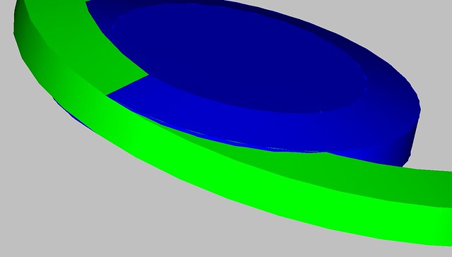
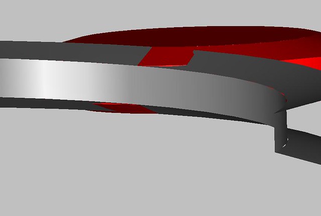
Something like this?

I drew these up years ago.. I think it was a 1-5 acme. Blue is internal, red is external..
I wanted to see if it was possible to threadmill an Acme thread.. Threadmill dimensions
(spinning disc) are from a company (can't remember the name) that sells thread mills for acme
threads..

Internal, you could use a key cutter and come up with the same profile.
5406273439_f4d39b8453_z.jpg


5409772338_1967d5dea4_z.jpg
 
Something like this?

I drew these up years ago.. I think it was a 1-5 acme. Blue is internal, red is external..
I wanted to see if it was possible to threadmill an Acme thread.. Threadmill dimensions
(spinning disc) are from a company (can't remember the name) that sells thread mills for acme
threads..

Internal, you could use a key cutter and come up with the same profile.

Yeah, thats what I had in my mind.

Seamoss'es post got me. In what plane the flank angles are actually defined and measured?
Parallel to bore/hole axis or perpendicular to threadform itself? (If anyone understands what I'm after)
 
Yeah, thats what I had in my mind.

Seamoss'es post got me. In what plane the flank angles are actually defined and measured?
Parallel to bore/hole axis or perpendicular to threadform itself? (If anyone understands what I'm after)

I understand, and I also don't know the answer.. I would assume parallel to the center axis, at least
that is what all the diagrams I've ever seen show.

For instance, when measuring a PD with wires, the wires sit in line with the thread form, not perpendicular
to the central axis of the bolt/nut.
 
In my experience people only worry about it for Acme, where the effect is magnified, and in super critical applications. In the vast majority of cases the error is too small to matter. It also matters more if you're doing double or more lead, since the angle is so much steeper.
 
At least as far as metric and UN thread forms, the ideal thread form is defined parallel to the axis of rotation, not perpendicular to the lead helix.

Thats how I have also always imagined it.

AFAIK means that the angled seats for turning tool mentioned by Seamoss fix the clearance issue but introduce (very!)small error to threadform/flank angles.


I did try to calculate&draw the rake angle effect on external thread turning once on a paper but "oh boy" the thing got complicated.
There is at least 2 different factors involved, ie. cutting edge falling below center line, cutting tool width "presented" to work getting narrower because of interaction between rake angle and relief angles.
 
At least as far as metric and UN thread forms, the ideal thread form is defined parallel to the axis of rotation, not perpendicular to the lead helix.
Learn something new every day, I have always thought of them as small worms (occupational hazard :)) Thank you.

MattiJ - I have seen some papers on the error you are describing, but it was related to larger threads on larger worms. And even there the 'profile deviation' was minuscule. Running a bronze wormgear against a hardened steel worm, I didn't see the point except for maybe academic interest. Sorry I can't find those references but it was online.

Otherwise, if you want to look into the math, Buckingham's Analytical Mechanics of Gears has a chapter on the contact patterns of worms made in different ways, the principles with threads are the same. That chapter is heavily into differential equations. Hope you like mathematics :)
 
hello :) please consider known the following :
... thread dimensions + tolerances
... tool ( thread mill ) dimensions

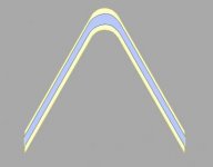
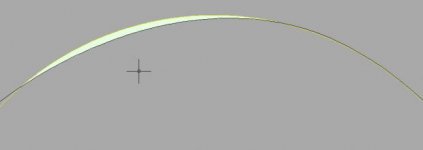
attached images shows rendered images for a real example :
...image 1 : cutting tolerance is 50% of theoretical tolerance, and is represented at the middle of the theoretical tolerance
...image 2 : expected profile ( black ) versus theoretical profile ( yellow )
...image 3 : expected left and right flanc angle deviations :)

expected profile can be rendered, and expected deviations from iso profile can be calculated

comparing this deviations with the basic tolerances should give an idea about the reliabilty of the cutting process / good day :)
 

Attachments

  • 01.jpg
    01.jpg
    7.1 KB · Views: 105
  • 02.jpg
    02.jpg
    5.6 KB · Views: 90
  • 03.jpg
    03.jpg
    5.6 KB · Views: 104
Learn something new every day, I have always thought of them as small worms (occupational hazard :)) Thank you.

MattiJ - I have seen some papers on the error you are describing, but it was related to larger threads on larger worms. And even there the 'profile deviation' was minuscule. Running a bronze wormgear against a hardened steel worm, I didn't see the point except for maybe academic interest. Sorry I can't find those references but it was online.

Otherwise, if you want to look into the math, Buckingham's Analytical Mechanics of Gears has a chapter on the contact patterns of worms made in different ways, the principles with threads are the same. That chapter is heavily into differential equations. Hope you like mathematics :)


The American Society of Mechanical Engineers have published a few papers.


Effect of Thread Milling Penetration Strategies on the Dimensional Accuracy | Journal of Manufacturing Science and Engineering | ASME DC


Back
Top