But what does your tool look like?
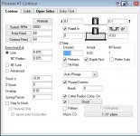
Say I have created a tool that looks like this:
The largest diameter on this tool is 1.5". Small diameter is 1". When using the same parameters you have, this tool will never hit the edge with the tool I created.
That's why I get the diameter off the optical presetter. If my cut depth is .03", I'll get the diameter .03" from the tip of the tool. I can then use a negative stock value to get the desired chamfer, or simply go deeper. Either way.
I guess I forgot to mention above; the offset curve method is *very* useful if the chamfer does not go all the way around the part, and may trail off in a spot. Not run off an edge, but a constant decrease in chamfer depth or other similar feature is a good candidate for offset curve.