What's new
What's new

MRR optimization - Is this really as fast as it looks?

Zahnrad Kopf

Diamond
Joined
Apr 5, 2010
Location
Tropic of Milwaukee
We have a job coming on the mill that requires removing most ( or at least a large majority ) of the material block. In researching some new tooling options,

I stumbled across this video, which caught my attention. Take a look at the tool path starting at 2:45 through 3:14. We are looking a this face mill anyway, and so this looks attractive to me for our purposes on this next job where we effectively need to remove an area of a corner/end of a block that is 3.75 wide by 6.312 to a depth of 4.430" and then do the same on the other end of the block, effectively creating an island in the middle.

I was planning on just creating a high speed adaptive roughing type tool path to chew it away, but this strategy seems to look faster. Anyone actually tried this? I know it has come up in discussions before, but I am curious of its actual speed/time beneifits.


Are you referring to the plunge milling? I worked at a shop that did that on Iconel, but have no idea what speeds and feeds were. I know it was a 2" face mill style tool with tangential(?) inserts.
 
Looks like a Cat 50 or HSK160 spindle there. You'd need a really stout machine to replicate that kind of performance. Your high speed tool path seems more predictable.
 
Are you referring to the plunge milling? I worked at a shop that did that on Iconel, but have no idea what speeds and feeds were. I know it was a 2" face mill style tool with tangential(?) inserts.

Yes. That's exactly what I am referring to. :cool: The block is D2. So, it can present its own issues.
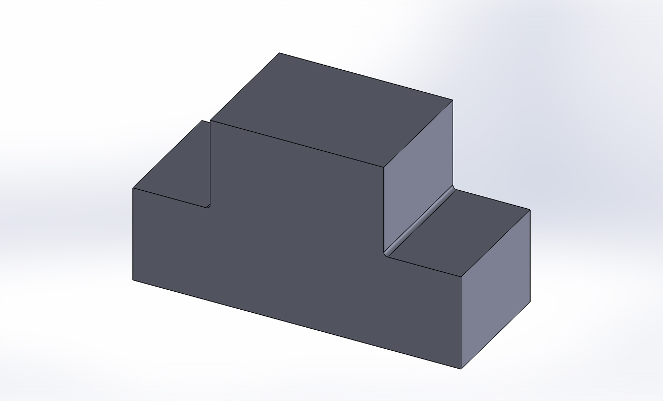
Will look like this when we're done.

Block.JPG
 
Looks like a Cat 50 or HSK160 spindle there. You'd need a really stout machine to replicate that kind of performance. Your high speed tool path seems more predictable.

Absolutely agreed about your point. But apples to apples in the same machine ( whatever that machine is ), is this method any faster than the alternatives?
 
Good question. Popular wisdom is that the fastest MRR tool is a drill, so maybe there is some merit to it.

EXACTLY my thoughts and why I am wondering.

I have to also wonder about how it is generated. I'm guessing that one could create hole features and use a drilling cycle to plunge them all out....
 
You have to go by the Cubic Inch per Minute numbers, not appearance. I posted a question and video here earlier this year about plunge roughing in aluminum and pretty much got laughed at by the HSM guys that I needed to ditch my proven method with a 3" cutter and switch to a 1/2 endmill because what I was doing 'looked slow'. Plunging doesn't seem to be very popular, and I've found most CAM systems only offer it in the highest version of their software with moldmaking features.

Here's a good video presentation on plunging -
Plunge Milling: High Volume Roughing on Your Machine, Part One - YouTube
 
I use plunge milling a fair bit. All else being equal it works far better on a 50 taper spindle than on a 40, but it's not entirely out of the question on the smaller spindle.

In terms of MRR, it's faster than high feed, but there are drawbacks. It still requires a profiling pass, so in many cases just going with the high feed is much quicker.

The biggest issue with plunge milling on a smaller spindle is touching the floor. Most plunge milling cutters are the same or similar to high feed - in many cases the same tool is used for both. The shallow negative angle on the bottom leaves ridges on the floor that can cause deflection and large torque spikes when touching the floor. 50 taper spindles handle this much better than 40. Plunging right through the material works better.

The summary version is that things need to be scaled down a bit more than you might think when comparing 50 to 40 taper plunge milling.

I've never had an opportunity to try a big plus spindle for this but I suspect it would be a big advantage.
 
You have to go by the Cubic Inch per Minute numbers, not appearance. I posted a question and video here earlier this year about plunge roughing in aluminum and pretty much got laughed at by the HSM guys that I needed to ditch my proven method with a 3" cutter and switch to a 1/2 endmill because what I was doing 'looked slow'. Plunging doesn't seem to be very popular, and I've found most CAM systems only offer it in the highest version of their software with moldmaking features.

BOLD added by me, above.

I don't really care about "popular". There are a LOT of people just now finding out about HSM tool paths and thinking it's their calling in life to start making youtube videos espousing their knowledge. Honestly, I simply could not care less. I want to know real numbers and performance and unless someone has been there and done that, their income depends on how it is done, or they have some other manner of vested interest in actual performance and how it relates to the bottom line dollar and throughput of a machine, I go tone deaf very quickly.

And if I can learn something along the way, even better. :)
 
Both of you replied while I was composing the other resposne, so apologies for not seeing them more quickly.

wouldn't that be what plunge roughing is?
I think it's a strategy or what ever they call it in bobcad

Did not know that... Thank you. I'll check it out. We have BobCAM...
icon14.png


I use plunge milling a fair bit. All else being equal it works far better on a 50 taper spindle than on a 40, but it's not entirely out of the question on the smaller spindle.
In terms of MRR, it's faster than high feed, but there are drawbacks. It still requires a profiling pass, so in many cases just going with the high feed is much quicker.
The biggest issue with plunge milling on a smaller spindle is touching the floor. Most plunge milling cutters are the same or similar to high feed - in many cases the same tool is used for both. The shallow negative angle on the bottom leaves ridges on the floor that can cause deflection and large torque spikes when touching the floor. 50 taper spindles handle this much better than 40. Plunging right through the material works better.
The summary version is that things need to be scaled down a bit more than you might think when comparing 50 to 40 taper plunge milling.
I've never had an opportunity to try a big plus spindle for this but I suspect it would be a big advantage.

Thanks, Gregor. I appreciate the weigh-in. I have a few options and will compare it against other tool paths as far as calculations go, but I am interested in finding out some general starting parameters to try.

Turns out that it is an option in the CAMs available to me, but I have been "blind" to it for simply not ever having a situation that called for it. Who knew? :scratchchin: :o
 
Funny timing; I'm also seriously considering a plunging operation to rough a production part. I also see in other forums where guys say a good tool/holder setup doing HSM can't be beat.
Direct to Z's question; I think the plunge operation would work amazingly well in D2...whith the added benifit to not having a million inches of approaches while stepping down his simple geometry block.
 
Hi Zahnrad Kopf:
The thing that kills my interest in insert cutters very quickly is the limited DOC together with the cost of replacing the inserts.
As soon as the material is more challenging to cut than aluminum, I start to look much more closely at the cost per cubic inch of material removal than only at the MRR of a brand new cutter with great chip control which is what the videos always love to show.

One of the really big things I've noticed after switching from insert cutters to smaller diameter solid carbide endmills is the drastic reduction in endmill consumption: I'm getting this benefit without any real penalty in MRR on the kinds of parts I mostly cut, so it feels like a win to me.
As an example, I used to rough a 304 stainless part with 1" diameter 3 flute Sandvik Coromant insert cutters and would typically use a set of inserts for two parts.
The cutter was really crapped out by the end of the second part and I had to grit my teeth not to change it out before part #2 was done.
Last time I cut them with 1/2" solid carbide endmills I cut 10 with the same cutter in about the same time and still had plenty of life left in the cutter.
The inserts for one changeout cost about the same as the solid carbide endmill.

So I'm not much of a fan of going back; mind you I'm milling on a floppy little Minimill.
If you've got a nice stout machine and have to remove a lot of material from a large surface area your best strategy might well be to run a big cutter at shallow DOC and accept the cost and time penalty of replacing inserts more often.

Obviously, a lot will depend on how hard your material is, and how well you can manage the chips, but wide flat plates seem intuitively to be better suited to insert cutters than parts which need to be profiled to any substantial depth.

On a last note; yeah I like plunge roughing for a limited sort of operation too, but there are two things that work against it as a general default strategy in my mind.
First there are an awful lot of repositioning moves during plunging.
That wastes time and leads to lots of strain on the cutting edges when the cut begins and when it slams onto the floor as it ends.
Second is that chip control is more difficult in many part geometries.
Through spindle air can help a lot but the risk of chip recutting and consequent catastrophic cutter failure is always present.
When it blows it's expensive and much harder on the machine than when a dinky little endmill gives up the ghost.

Cheers

Marcus
Implant Mechanix • Design & Innovation > HOME
www.vancouverwireedm.com
 
I use plunge milling a fair bit. All else being equal it works far better on a 50 taper spindle than on a 40, but it's not entirely out of the question on the smaller spindle.

In terms of MRR, it's faster than high feed, but there are drawbacks. It still requires a profiling pass, so in many cases just going with the high feed is much quicker.

The biggest issue with plunge milling on a smaller spindle is touching the floor. Most plunge milling cutters are the same or similar to high feed - in many cases the same tool is used for both. The shallow negative angle on the bottom leaves ridges on the floor that can cause deflection and large torque spikes when touching the floor. 50 taper spindles handle this much better than 40. Plunging right through the material works better.

The summary version is that things need to be scaled down a bit more than you might think when comparing 50 to 40 taper plunge milling.

I've never had an opportunity to try a big plus spindle for this but I suspect it would be a big advantage.

This X2. Another thing to keep in mind is, on a profile it's great, but I have seen people try opening up a large pocket---not so much with the chips. The main advantage is that the load is directed to the spindle instead of side load. We use a very specific KM product called 'Z AXIS PLUNGE MILL. So not really designed for anything else, on 50 T machines but we also run some 30 taper machines and use plunge milling, with less eyeopening results, but still works. Just use less feed and more stepover to get the load closer to the center of the tool.
 
Hi again Zahnrad Kopf:
I just had a closer look at the parts you are trying to cut.
Have you considered bandsawing these to rough them out and saving the leftover lumps instead of turning them all into chips?
An upright Roll-In type of bandsaw would make short work of roughing them; maybe your steel vendor could supply you with pre-sawn blanks if you don't have and can't justify such a saw yourself.
It'd be nice not to have to buy all that steel and then turn it into chips.

Dare I say you might even be justified in costing out how the numbers would stack up to blast through them on the wire EDM with 0.012" wire.
It's counter intuitive I know but I've been surprised before; especially if I load up the table and let it burble overnight.
Yeah it takes longer but if your only real cost is power and wire and you can nest the parts to use half the D2 for the job, you might have a winner.

If this thought turns out to be nutso, you can dope slap me at your leisure but I'd be awfully tempted to run the numbers, just for fun!!

Cheers

Marcus
Implant Mechanix • Design & Innovation > HOME
www.vancouverwireedm.com
 
First time I heard of plunge milling it was an article on roughing out tons of material on older big machines with geared spindles and tons of torque available. In that scenario it made a lot of sense as those machines would not have done HSM well. Finish on another machine.
 
in my shop in a wide open scenario like that I would have a 2 inch 1/2 round insert copy mill, air blast thru spindle- and rip it.....whatever the inserts will take. then go back with a 90 degree 2 inch indexable or a long endmill to finish the wall.
 
Hi again Zahnrad Kopf:
I just had a closer look at the parts you are trying to cut.
Have you considered bandsawing these to rough them out and saving the leftover lumps instead of turning them all into chips? An upright Roll-In type of bandsaw would make short work of roughing them; maybe your steel vendor could supply you with pre-sawn blanks if you don't have and can't justify such a saw yourself.
It'd be nice not to have to buy all that steel and then turn it into chips.
Dare I say you might even be justified in costing out how the numbers would stack up to blast through them on the wire EDM with 0.012" wire.
It's counter intuitive I know but I've been surprised before; especially if I load up the table and let it burble overnight.
Yeah it takes longer but if your only real cost is power and wire and you can nest the parts to use half the D2 for the job, you might have a winner.
If this thought turns out to be nutso, you can dope slap me at your leisure but I'd be awfully tempted to run the numbers, just for fun!!
Cheers

Marcus
Implant Mechanix • Design & Innovation > HOME
www.vancouverwireedm.com

Hi buddy,

Yes, I have actually considered both. The bandsaw is fairly unattractive to me for it being D2. There is not a lot of these, but enough to make me not want to do that. As for WEDM - you know I already thought of it. :cool: It is a favorite for this kind of application and has the added benefit of leaving a finished surface. The smaller problem is that it is right at the capacity of our machine at 6.31" thick. The larger issue is that it works out to approximately 12 hours of cut time PER SIDE. It would be 24 hours or more per part. Given the milling times and costs, it sure seems a waste. NOW, having said that, I did the calcs with our standard set up - which is .008" wire. Changing over to .012" would indeed improve things, but I think not enough to warrant the effort. I'm happy to be wrong about that, though.

in my shop in a wide open scenario like that I would have a 2 inch 1/2 round insert copy mill, air blast thru spindle- and rip it.....whatever the inserts will take. then go back with a 90 degree 2 inch indexable or a long endmill to finish the wall.

That is indeed similar to the plan for now. I'm just trying to see if we can improve upon it.
 
This X2. Another thing to keep in mind is, on a profile it's great, but I have seen people try opening up a large pocket---not so much with the chips. The main advantage is that the load is directed to the spindle instead of side load. We use a very specific KM product called 'Z AXIS PLUNGE MILL. So not really designed for anything else, on 50 T machines but we also run some 30 taper machines and use plunge milling, with less eyeopening results, but still works. Just use less feed and more stepover to get the load closer to the center of the tool.

Hi Rob,

I posted a picture of the basic part shape. The reason I became interested in this is because the cuts are located on the outsides of the block. Meaning, chip evacuation is enhanced by their ability to fall off or be blasted out of the way by coolant/air.


Back
Top