What's new
What's new

need help for turning a long part with thin walls

dany_boy

Banned
Joined
Feb 10, 2018
Hello !

I would appreciate any suggestions for clamping and turning part from attachment.

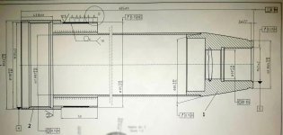
Parts are welded, and after that all those tolerances and conditions must be achieved, as easy & fast as possible.

cnc turning experience with long parts with thin walls, buckling control, low clamping forces, steady rest, is more than welcomed.

I have to adapt the process from classical machines to cnc machines, and i would appreciate any help.

Thank you in advance !
 

Attachments

  • m1.jpg
    m1.jpg
    95.2 KB · Views: 542
That looks absolutely miserable..

i would appreciate any help

Bring a six pack to work, or, since you're in France, a bottle of wine..


How much of this is being machined before welding? Or is ALL the
machining being done after welding, and also, I don't see a dimension
where the thin wall is machined down, how tight is that...
 
As above clarify how much of it is machined pre weld vs post weld.

What do you have for Cnc equipment and how many are you making?
 
I once had to turn .005" off a .75" od x 12" long SS tubing with a .050" wall. It chattered crazy. I bought some lead bird shot, capped both ends, and filled it about 80% full. This left room for the shot to move and absorb any vibration. Worked like a champ. If I packed the tube solid with shot, I still got chatter. I didn't try it, but adding oil to the shot, (like way oil) might also help.
 
Doesnt look too bad other than the .100 wall thickness on the tube. Whats the material size before you machine it? Using a steadyrest, do all your I.D work before you turn any of the welds off or any of the O.D. then find a bullnose and use i.d. grip jaws to turn the rest of it end to end. Gona have to mess w speeds and feeds a lot to keep it from chattering but reallu doesnt look to bad. Also look into using a follow-rest to help w chatter.
 
How would you do it on a manual? Just do it as close to that on the CNC.


Sent from my iPhone using Tapatalk
 
Fusable metals are your best friend for jobs like this.
If you dont know what I'm talking about.... research it.

My coworkers thought I was setting up for a kids birthday party when I ordered elongated party balloons, silly putty, and a s'hit ton of electrical tape.
 
Bring a six pack to work, or, since you're in France, a bottle of wine..

yeah, so true ! many machinists like to drink just a little ( more ) bit

i never met a vegan machinist :)

How much of this is being machined before welding?

this is one aspect that i must think of

What do you have for Cnc equipment and how many are you making?

hello newton : cnc lathe with steady rest and tailstock; few thousands

thank you for sharing that video

This left room for the shot to move and absorb any vibration.

hello jcoehlo, only when the part will be on the machine i may notice cutting vibrations

at this moment i have to design the process, and i am considering chatter

Using a steadyrest, do all your I.D work before you ...

hello Dan, i am considering this variant, also i am considering doing all the OD work before

In both cases, i am considering cutting the o81[+0.14] before the welding, so to avoid boring it after; i hope it will work

How would you do it on a manual? Just do it as close to that on the CNC

that's tricky : for example on a classic lathe i may negociate the tir and the clamping force with the chuck; cnc hidraulics chucks are not negotiable, and this means that the tailstock ( or the steady rest ) will have to deliver more force

i have to deliver, on the cnc, the "gentle hands" setup specific to a classic lathe

my target is a faster and long term reliable setup, comparing to classic lathes, with similar clamping forces

Fusable metals

hello macds, i am afraid i can not change material. Please, what are the arguments to do so ?


Thank you all for your sugestions :)
 
Last edited:
I guess it wouldnt matter o.d. or i.d. first. I just prefer to finish the o.d. last on things like this that way u dont risk damaging the finish on the o.d. after its machined and since thats the thinnest area on the part it might help to leave as much stock it as u can to help prevent chatter while machining the i.d.
I know u said it all has to be done on a cnc machine but maybe if theres not much stock coming off the i.d. u could have the longer smaller inside diameter of it it honed out?
Also just curious what is this thing used for?
 
Is this friction welded?

There is reason to do ID first, as then you can then mount it on an expanding mandrel with a live center support for the OD, you have the entire tube length as a clamping surface then so can use very light clamping pressure so as to control distortion.
 
No, you dont change the part material.
You use a zero expansion fusable metal to fill the body\openings to enable machining of thin walls.... seriously, research it.
The stuff melts at VERY low temperatures, so you dont end up putting heat into your workpiece.
Stay away from the alloys that contain lead and cadmium!
 
I'd use an expanding mandrel with a tail stock on the OD. For the ID, I'd ask if there is a part that you can use on the OD prior to turning as a datum point, then make your soft jaws to repeat there? Obviously this approach would mean ID first, OD second.
 
Some info missing from part#1, was it completed as a part before welding with your current process?

I sometimes live a sheltered life...what are the row of 6's and the 131 in the upper left referencing? weld symbol?
 
The 131 in the tail is a callout for MIG welding. The circle above the line means it is a projected weld (to the OD). The Check mark with the 12.5 is a bevel call. I may be wrong, but for welding I'd read that as six 6mm wide, 6mm tall MIG beads around the circumference of the part?
 
I'd use an expanding mandrel with a tail stock on the OD. For the ID, I'd ask if there is a part that you can use on the OD prior to turning as a datum point, then make your soft jaws to repeat there? Obviously this approach would mean ID first, OD second.


As I read and looked at the drawing I though expanding mandrel too. On the big end and You could make a plug with a shoulder on the small end about 1" long. Could be a sliding fit with a center hole in the outside end. Knurled the out side so you can pull it out. Rick... GMTA lol...
 
Seems like a lot of info is missing (including some drawing symbol knowledge on my part) --

1) I don't see any material call-outs (steel, aluminum, unobtainium?);
2) the 20 or so ")" marks at about the 87mm diameter distance on each side of centerline are symbols I'm unfamiliar with;
3) the application (perhaps something optical given the relatively large diameter 2 mm pitch threads?)and intended finish of the part would be helpful to know;
4) Rick Finsta's clarification of 6 MIG weld beads (6mm x 6mm each), if true, raises huge concerns about weld distortion in my mind;
5) seems like a serious design-for-manufacture review for production of several thousand parts is warranted! I would want to address realism of all tolerances (the barrel of a telescope might really have looser diameter/concentricity tolerances, for instance) as well as considering alternatives to 6 MIG weld beads on something approx 2 feet long with less than 0.10 inch wall thickness (TIG, laser or e-beam welds or brazing to minimize distortion, or even epoxy joining to the thin wall tube portion). Some of these alternative assembly methods may allow little or no machining of the final unit while meeting necessary tolerances for the function.
 
Ha, of course. I'm usually pretty good at picking up initialisms but I'm so new to a lot of machining jargon that my head went that direction.

Lee J I am not even close to 100% with welding blueprints as I do all one-off stuff, no production jobs, so take my interpretation with a large grain of salt.


Back
Top