What's new
What's new

Oval to round transition with slight undercut, lollipop EM?

Richard/SIA

Cast Iron
Joined
May 13, 2007
Location
No. Nevada
Only have a three-axis Fadal mill.
Finally about to have time to do a project for myself!
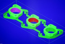
Motorcycle ITB's to Porsche IDA-3 manifold adapters.
The ITB's are oval, the Porsche intake is round.
The ITB oval is narrower than 40mm in Y but longer in X.
So the taper at X is simple but the slight undercut in Y has me wondering about using a lollipop mill?
Aluminum plate, the transition is only .750" deep and 40mm at the bottom.
I've found 3/8" cutters at a decent price.
I'm told that programming this would be a Bear, why?

I could just flip the part and make the blend from both sides but I think setup and cycle speed would be faster if I can do most of it from one side.

Price of the cutter aside, what is the advice on these cutters and this operation?
 
Got a model or at least crayon assisted drawring?

a simple idea for being able to flip and have it match well is to use "fixture material" off the ends with some dowel pins to locate the part. If you model and program well you wont even have to relocate z to match. have your rotation plane in the center of the model. This will be cheaper than the lollipop but I like the idea of single setup so get us a model to gander at.
 
Hi Richard/SIA:
The programming problem is that many CAM softwares cannot process undercuts at all and will simply ignore those surfaces when you try to put a toolpath on them.
Softwares that can recognize undercuts and process them will be quite restricted in the toolpaths that you are allowed to use.
So the limitation is mostly a software limitation and depending on the geometry and your software it can be an impossible problem to solve conventionally.

If your software is limited in this way, you have an option to overcome this limitation, but it is a "cheat" so you have to be very careful to control your entry and exit moves (with hand coding if necessary) so you don't gouge the part on entry or on exit.

Basically you need to lay contour lines on your undercut surfaces and program each of them line by line, then stitch the whole works together manually again with the caveat above.

I've successfully done it this way but it take a long time to do, it is error prone, and it is horribly inflexible in that a programming change is a bear to implement.

So your happiest option is to find someone who has the programming capability to do it for you or else to invest in the proper software if you don't already have it.

HSMWorks can do it with its 3D contour toolpaths, obviously high zoot software like Powermill and Hypermill can do it...my ancient version of Mastercrap cannot, nor can my ancient version of Featuremill.

So it's either the cheaper, more labour intensive approach or the outrageously expensive "Buy it in a Box" approach.
Your patience and your wallet will make the decision for you.

Cheers

Marcus
Implant Mechanix • Design & Innovation > HOME
Vancouver Wire EDM -- Wire EDM Machining
 
Mastercam has some 3-axis paths that will undercut with lollipops. Flowline is a good one. Sounds like it should work fine if you can get it programmed; you didn't say what CAM software you have?

programming undercut surfaces in Mastercam - YouTube

In theory if you're good at mathematical geometry you could do it by hand with a macro. Formula for a circle at the top, formula for the ellipse at the bottom, weighted average for each stepdown.
 
I take the chance of sounding like an idiot here, as I'm not that up on 3D printing... but I was just delving into it for some prototype parts and it sounds like the 3D printers run on G-code. The "slicing" software for them is a free download. If you have the model, put it into the slicing software and you get a layer by layer g-code file. That could be copied and add a G41/42 offset and you could cut the desired path with your lollipop cutter? Yes? No?
 
Hi Brian:
That's an interesting an innovative approach to the problem.
Of course, all depends on the truth of your hypothesis that there are 3D printers out there that run on G-code and of the correct flavour that the OP's machine tool can run it.
Arc management is the obvious gotcha here; if it requires incremental instead of absolute or vice versa it's going to make a mighty funny toolpath.
One of my machines is weird that way; the Defiance mill goes nuts if I try to post Haas code to it and it's all about how it handles arc statements. (It does other weird shit too, but not relevant to the OP's problem or your very creative solution)

So with that caveat; I like the idea... you're well to the left of the conventional box in your thinking!!:D

Cheers

Marcus
Implant Mechanix • Design & Innovation > HOME
Vancouver Wire EDM -- Wire EDM Machining
 
Well, obviously there would be a lot of investigation needed. I'm sure the printers calculate a specific bead diameter for their extruded path... but if you could get pretty close to the centerline path, then using G42 and G43 you should be able to offset for half the lollipop diameter. Might have to add a few lead in/lead out arcs to make sure you don't gouge the part coming back out of it.

It was just the thought that the paths for 3D printing are pretty much just waterline paths in CAM... so it might be worth playing with Cura (I think that's one of the common softwares for slicing) and see if you could come up with a tool path.

From what I've been reading and watching on youtube, the machines take g-code. It might be all straight-line moves and huge gigabytes of program, as they usually deal with STL files anyway, but worth looking into.
 
Is it different than XYZ values and G00/G01/G02/G03? I mean yes, every brand of machine has a few oddities in their g-code, but once you get into the meat of the program, code is pretty much code.... At least I'm assuming that's the case, and you know what assuming can get you into...
 
The CAD is incomplete as I'm still trying to learn MC in the evenings on another users system.
The lollipop end-mill was in his tool library, I had never heard of them before.

You probably cannot really see the reverse taper, it's only about 5mm.
 

Attachments

  • IMG_2310.jpg
    IMG_2310.jpg
    41.8 KB · Views: 110
Well, as long as you can get the program, machining it shouldn't be much of an issue. Although, a 3/8" cutter isn't going to work if you have 5mm of over hang. Shank will have to be 10mm smaller than the ball on the end, so you are probably looking more like a 3/4" ball with slightly under a 3/8 shank.
 
I have had to do this numerous times. For very simple geometry and cutters the Mastercam Flowline tool path will get the job done. I think it will only support lollipop cutters and you need to use the archaic flowline lead in and lead out, which always takes me some time to figure out.

In your case, there is no way to do this with a lollipop cutter because your overhangs are too large. The way I deal with this is to use a full radius keyseat cutter. In your case a 1" cutter with a 3/8" shank will get in there nicely. I would go with a .250 thickness on the cutter with a .125" radius (full radius). Mastercam will choke if you try and surface with this, but there is a nice work around. Under create curve, there is an option to create curve using flowline. This will create clean geometric curves in on the surface with whatever spacing you want. In your case, I made curves in .015" increments. Now that you have curves, you can program off of those with ordinary 2D contours. If you mess around with your linking parameters (in this case all of them should be set at incremental Z-.125 because of the radius, except Clearance which should be a number above the part Start and End Only), you can still get a pretty efficient program. Keep in mind you will need to really work on your lead in/ lead out to ensure that you don't gouge the part in entry or exit, and this may or may not require breaking the curve at a mid-point.

Untitled.jpg
 
I programmed such a part on a Fadal about 25 years ago using the Fadal macro language which is a derivative of Microsoft Mbasic. I did it parametrically letting the CNC calulate the tool path on the fly. I did this a lot.

Here is a thought on how to do this in Cam that can’t do an undercut. Program the part flipped over with wide side up and use the bottom of the surface as Z zero. Generate the toolpath and in a G-code editor search and replace all +Z with -Z.


Back
Top