Hi Robert:
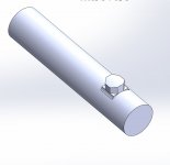
No you cannot make that geometry on a lathe or on a milling machine for that matter.
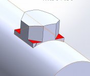
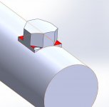
You can only make an approximation of it and the problem area is the junction of the octagonal boss with the cylinder.
The only way to make this geometrically correct is to sinker EDM it with an electrode that has the proper shape.
The obtuse angles between the boss and the cylinder could be faked using a Mill-Turn machine like an Integrex, but not for cheap.
The cheapest way to fake it is to accept a semicircular ditch at the foot of the boss and walk around it with a ball cutter.
Any decent Y axis lathe should be able to do that.
The depth of the ditch below the cylinder surface would obviously depend on the diameter of the cutter that was used and how much material can be tolerated at the root of the boss.
To those who commented that it was a dumb design...yeah I agree.
Cheers
Marcus
Implant Mechanix • Design & Innovation > HOME
Vancouver Wire EDM -- Wire EDM Machining