What's new
What's new

Wiring problem: Bridgeport CNC motor won't stay on unless I hold switch.

swflcnc

Plastic
Joined
Jan 26, 2016
Wiring problem: Bridgeport CNC motor won't stay on unless I hold switch.

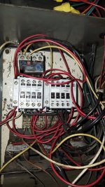
I just finished replacing a Contactor in my Bridgeport 2J head 2HP CNC mill with varidrive. When I was diagnosing the bad contactor, I found a loose wire and believe it may be the problem. The contactor was frozen in the open position. There are 2 Contactors with an interlock wired as a reversing contactor. When I turn on the starter switch left the low/forward (or high/reverse) works fine, but when I turn the switch to the right the contactor will only stay engaged if I hold the switch to the right. The missing wire is on the left interlock and stared on my drawing. I have pictures as well as I drew out the wiring as best I could. I don't think I can upload a picture large enough to be of use but I'd be happy to email them if someone can help. So far I haven't been able to find a relevant thread on the site.

I am not an electrician, but I do know the basics. I understand that the engaged contactor should be able to also close the control circuit until the current is broken with the Stop button. My problem is that this setup also has the CNC controller and other components that has made it much more complex.

As for my drawing:
Orange/black goes to High Speed switch.
Orange goes to low speed switch.
Red/black is common from High/low speed switch.
Red is a Stop switch.
White indicated on the sheet go to the thermal overload relay (pin 96)
From the bottom of the page, the DC current comes from my CNC controller I believe. The 2 white wires from my Emergency Stop button also go to the CNC controller and stop all axis movement as well.
 

Attachments

  • cnc wiring 4 (1).jpg
    cnc wiring 4 (1).jpg
    16.6 KB · Views: 428
  • cnc wiring 3.jpg
    cnc wiring 3.jpg
    17 KB · Views: 431
  • cnc wiring 1.jpg
    cnc wiring 1.jpg
    16.6 KB · Views: 441
  • cnc wiring 2 (2).jpg
    cnc wiring 2 (2).jpg
    18.3 KB · Views: 438
  • cnc wiring 1 500.jpg
    cnc wiring 1 500.jpg
    103.6 KB · Views: 634
Last edited:
If you google search motor starter start stop circuit you should be able to figure this out. you just have the extra contactor for the reversing.
 
Thanks for that advice. Unfortunately I have already done that and a simple start stop circuit doesn't seem to cover my situation. There are 3 relays, 2 contactors, a center interlock and interlocks on the outside of the contactors, 2 stop switches on the main panel, and a stop switch that somehow connects to the computer. The 4th contact on the contactors isn't even used in my situation where it is normally used in a more simple start stop circuit. If I am overcomplicating it then please let me know. Where you able to see the pictures? I could only upload small files.
 
Only one pix opened for me..the one that looks like a bad hair day. Are the two clean mags the items you replaced? Did the problem crop up after you did the work or was that exact same problem the reason for your work!

As you have found out, 3 wire control involves a 'make' command and a 'maintained' command. The maintained closure is on the device that is being affected by the make command. It looks like those two mags have auxiliary contacts tagged onto their side. Often those have both NO/NC functions and you must connect to the proper screw or you'll get the wrong outcome.

Fix the pix if you can and dig around a bit more. The thing will pull in, it just won't maintain...your half way there.

Stuart
 
This is were neat wiring makes this stuff a lot easier to chase through. Nothings harder than badly wired unlabelled wiring all the same colour to make simple fault finding go from a 5 minute task to a multi hour hunt. Its not a dig, its just hard to chase stuff through as you have it there. Even if all you have is the same colour wire, some simple different colour bands of electrical tape on em can soon make them a lot faster and easier to pick out.

Assuming the motor runs both ways correctly whilst holding the start switch in, but only interlocks one way, you just need to draw out what you have as the conrol logic - switches. Like this, posting that here we can probably help. Saying that once you have drawn it, you can probably also see why its wrong too! There is more than a few ways to do this with the parts you have there. hence it becomes hard to offer safe accurate advice. It may well be that each direction relay needs its control NO contacts wired in parallel so one or the other closes the run circuit - maintain command part. Normally its these contacts the start button in-effect closes through a different loop which can be as simple as a pair of wires off each side of those contacts, through to providing a live or neutral feed from a different source.
 
I could not get the pictures to all come up for me, but it sounds like you are missing a contact to latch in the switch. Without it you have what amounts to a jog switch. If you can get a better picture with cleaner diagrams I can help troubleshoot it. If not just look at the way the other side is wired. There should be a normaly open contact on a relay that the switch is wired to. That is the latch contact for the switch to stay on. If the other side is wired the same make sure the contact it is on is normaly open, not normaly closed.
 
Thanks for the help everyone. I will check on a couple things today and get back with some results tonight. I was not who wired the machine initially, which makes following the wiring even harder because I am not sure how it was meant to operate. I did draw out the diagram and followed each wire to try to simplify the circuits, but I was still not able to. Hope these pictures show up this time.

cnc wiring 4 500.jpgcnc wiring 2 500.jpgcnc wiring 3 500.jpg
 
Only one pix opened for me..the one that looks like a bad hair day. Are the two clean mags the items you replaced? Did the problem crop up after you did the work or was that exact same problem the reason for your work!

As you have found out, 3 wire control involves a 'make' command and a 'maintained' command. The maintained closure is on the device that is being affected by the make command. It looks like those two mags have auxiliary contacts tagged onto their side. Often those have both NO/NC functions and you must connect to the proper screw or you'll get the wrong outcome.

Fix the pix if you can and dig around a bit more. The thing will pull in, it just won't maintain...your half way there.

Stuart

I'm not sure what you mean by mag. Magnetic Contact? I replaced the springer JC09A310T contact on the left, only the part that has the 4 sets of contacts. It seems that the maintain command is switched on with the auxiliary single contact which is left of the springer. This is also where the wire comes from that doesn't lead anywhere. The aux contact does have both NC/NO functions but I did not switch any of the wiring.

Hope that answered everyone's questions. Should have another update tonight.
 
Got it fixed. Looked over my wiring diagram and it turned out to be one of the first connections I thought I had tried.

On another note, I found that the 3 relays below my contactors don't do anything to the circuit from what I could find. The DC leads from 1 & 2 come from my cnc controller, but the spindle will power up with or without the cnc controller on. However, I am able to turn the stepper motors off when I hit the emergency stop button. Is this what the relays are controlling?


Back
Top