- Joined
- May 14, 2009
By Jim Destefani, Senior Editor
Click Here for a free subscription to Cutting Tool Engineering magazine
Effectively drilling stacks, which have multiple layers of composites and metals, takes the right combination of tool and machining parameters.
From the F-35 Lightning II to the mammoth Airbus A380 and the Boeing 787 Dreamliner, composite/metal stack materials, most often consisting of multiple layers of carbon fiber-reinforced plastic (CFRP) composites and aluminum or titanium, have made a big a splash in the aerospace industry.
The Dreamliner, for example, is made up of (by weight) 50 percent composite, 20 percent aluminum, 15 percent titanium, 10 percent steel and 5 percent other materials. By volume, the aircraft will be 80 percent composite. Each 787 contains approximately 35 tons of CFRP, a good portion of it stacked in conjunction with aluminum or titanium alloys.on from CUTTING TOOL ENGINEERING Magazine, and is protected under U.S. and international copyright laws.

Courtesy of Boeing

Courtesy of Novator
Constructed of 80 percent composites by volume, each Boeing 787 Dreamliner (top photo) contains 35 tons of CFRP, and a good portion of it is stacked with aluminum or titanium alloys. An example of a metal/composite stack (bottom photo).
Aircraft manufacturers like stack materials because they combine metal's high strength with composite’s low weight and corrosion resistance. The variety of stack materials is increasing nearly as fast as the applications, according to Glenn Sheffler, project engineer at the National Center for Defense Manufacturing and Machining (NCDMM), Latrobe, Pa.
“Composite stack materials are replacing aluminum honeycomb materials, which consist of honeycomb paper sandwiched between layers of aluminum,” Sheffler said. “Often, stacks have various layers of composite, or a composite/metal stack combination, or foam or other core materials, and are then wrapped with composites.” Some stack materials may also incorporate a thin copper mesh designed to protect against lightning strikes, or other materials, he added. Overall stack thicknesses can vary from less than 1/4 " to several inches.
“Composite layup techniques also make a difference in machinability, and there could be multiple types of composites as well,” Sheffler continued. “To achieve the required strength in a composite structure, many times carbon fibers will require weaves and different layups in multiple directions, depending on the application.”
NCDMM’s involvement with stack materials began several years ago during development of manufacturing processes for the F-35. Since then, the organization has continued to work with defense manufacturers to develop drilling processes for stack materials.
“The material could be for an aircraft skin, it could be for weapons systems components—wherever they are trying to reduce weight,” said Joe Slusarcyk, project engineer. “As composites evolve, there will be more and more applications.”
Hole Strategy
NCDMM takes sample stacks sent to them by defense manufacturers and develops the best holemaking process for the materials. Engineers rarely see anything but test panels and for proprietary reasons may have only a generic idea of the materials making up the stack—something that makes the task of developing optimal drilling processes all the more challenging. “We drill holes until we find the solution,” Sheffler said. “That could be five holes or 5,000.”
Engineers use dynamometers to track cutting forces during drilling, and the optimal process is usually a tradeoff between low cutting force and tool life. “You want light cutting forces to minimize composite delamination and stress on the material,” Sheffler said. “Once you find a drill that gives you light cutting forces, it may, however, wear out after a minimum amount of holes. So we look for a happy medium between low thrust and tool life when developing a tool.”


Courtesy of Amamco Tool
Potential quality issues in drilling composite/metal stacks include size changes from one material to another as well as fraying and delamination. From top: clean hole, frayed hole, delaminated hole.
The process is complicated by variables other than the workpiece. Quality requirements, the order of materials in the stack and even whether the holes will be drilled using a CNC machine or by hand all make a difference in the needed tools and machining parameters. “Inspection requirements differ depending on the application,” Slusarcyk said. “Sometimes it might be only visual inspection as opposed to ultrasonic or some other technique.”
If a metal skin is on one surface, the drilling direction makes a difference. “Depending which side you enter, it can change the whole process,” Slusarcyk said. “Sometimes, if there’s a backing material, it is pretty stable. But in other cases you might have a thin skin that just blows out completely when you start pushing it. So fixturing is a very important piece of the puzzle.”
Tool Talk
Fortunately, cutting tool suppliers work with NCDMM and other organizations to develop the tools needed for effective drilling of composite/metal stacks. A frequent partner of NCDMM is Amamco Tool, Duncan, S.C.
“In drilling, cutting tool geometries vary based on the composition of the stack, and the geometries are endless,” said Peter Diamantis, Amamco plant manager. But, he added, there are some general guidelines.
According to Diamantis, the widely differing properties of materials in a composite/metal stack are the main obstacle to productive drilling. “Long point angles and long tapers work best when the drill exits the composite material,” he said. “Composites build up a lot of heat, which is not an issue in relatively thin material, but in thicker materials you need narrower flutes, wider gullets and tighter spirals to allow faster penetration.”
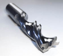
Courtesy of Cajero
The need to drill disparate materials such as CFRP and titanium results in unique tool geometries. This drill from Cajero has open, polished flutes to facilitate chip flow and double margins to support alignment and shave hole walls on materials that contract when machined. The combination point geometry is aimed at clean holemaking in fibrous materials.
Long taper angles tend to smear aluminum and cause drill loading, so knowing the placement of the aluminum in the stack is critical. “If the aluminum is on the back side of the stack, a high-shear drill with a sharp point angle will minimize the burr height of the exit hole,” Diamantis said. “If you are exiting on the composite material, you need to adjust drill geometry as well as feed rate. This is where drill/reamer combination tools and multifaceted drill points can work well.”
Diamantis calls composite/titanium stacks “the mother of all headaches” when it comes to drilling. “When drilling titanium, you typically want low reliefs, rake angles, feed rates and spindle speed—everything composites hate,” he said. “So you have to take into account everything, including the thickness of the stack and the number of holes you wish to achieve. The setup, the drill motor, using coolant or dry, hand or machine drilling—the entire process has to be evaluated.”
According to Diamantis, Amamco strives to produce holes in a single operation. “We do everything in one shot—we don’t drill and then come back and ream,” he said. “A ¼ " stack is not too hard, but thicker stacks become more difficult. So you have to provide tools that are specifically designed for drilling holes with a depth four and five times the diameter of the drill.”er materials you need narrower flutes, wider gullets and tighter spirals to allow faster penetration.”
CNC or Manual?
Alex Harding, operations manager for toolmaker Cajero Ltd., Kent, England, echoes many of Diamantis’ comments. “It’s essential that the end user work closely with the cutting tool supplier in identifying the correct drill for the application,” Harding said. “You have a responsibility to the customer, their machines and the $50,000 part that nobody wants to scrap!”
Harding emphasizes that the type of drilling operation—CNC or manual—can make a big difference in the cuting tool selected. “For CNC drilling of composite/titanium stacks, the best solution will likely be solid-carbide tools with through-coolant, although CVD diamond coating could also be considered,” he said.
Although coolant or mist is not generally used when drilling CFRP, which can swell because of coolant absorption, it can be preferred when drilling titanium, which tends to workharden.
Cajero advises customers to reduce cutting speed when drilling titanium to reduce heat at the cutting edge and minimize heat transfer to the composite material. “It’s also important to combine low cutting speed with the correct feed rate to produce small chips,” he said. “Long strands of swarf will recut the hole in the composite.”
For manual drilling, Cajero recommends that customers check to be sure their air tools have adequate torque at low speed. “It may also be necessary to consider ‘peck’ feed motors,” Harding added.
In composite/aluminum stacks, the company also recommends solid-carbide, CVD diamond-coated carbide or PCD drills. Tool life for the CVD diamond-coated and PCD drills should be upwards of 3,000 holes, Harding noted. “There may be a problem with swarf control depending on the aluminum alloy,” he said. “If so, a peck cycle may be needed to break the swarf in both CNC and manual drilling.”
Like Amamco, Cajero focuses on producing drills to achieve tight tolerances without a secondary reaming operation. “However, we can produce special drills that have a combination drill/reamer geometry for producing close-tolerance holes,” Harding said.
Diamond Veins
Although it’s well known that diamond drills work extremely well in CFRP, they can be equally productive in stack materials, according to Precorp Inc., Spanish Fork, Utah.
Precorp produces PCD-veined drills by first slotting a carbide blank and then inserting PCD powder in the slot. The blank is then placed in a high-pressure, high-temperature press to compress the powder and bond diamond crystals to each other and to the carbide blank. The PCD-veined nib is brazed to a solid-carbide shank and the tool is ground to the desired geometry.
The patented process permits tool geometries impractical or impossible using conventional PCD inserts, according to Rich Garrick, company president. “Precorp wanted to develop a common drill that could be used for all material stacks, to maximize life and minimize cycle time in CNC drilling as well as pneumatic, power-feed environments,” he said.
Courtesy of Allied Machine & Engineering
AMEC’s PCD tools for CFRP and stack drilling applications feature sharp cutting edges and achieve the required rake by positioning an insert in a tilted pocket.
For CNC drilling applications, the company’s PD series drills use a flute form with a heavy web and a wide flute opening to enhance strength and chip evacuation. Double margins improve hole roundness and stability in bushings. Recommended starting-point machining parameters for the tool are 200 sfm and 0.003 ipr in composite and aluminum, and 60 sfm and 0.002 ipr in titanium. In composite/titanium stacks, speeds and feeds are adjusted for each layer.
For manual drilling, Precorp’s CMD drill comes in piloted and unpiloted designs. Its point design is aimed at allowing rapid centering, and, once the drill is engaged in the cut, minimal force is required by the operator to finish the hole, Garrick said.
Another producer of PCD and CVD diamond-coated drills for stack drilling applications is Allied Machine & Engineering Corp., Dover, Ohio. Product Manager Rob Brown said upsharp geometries work well for many aerospace applications. “The potential drawback with coating is the diamond is usually pretty thick—10µm to 12µm,” he said. “That’s why we’ve developed some PCD drills as well, because you can get a true sharp edge.”
Unlike PCD-veined drills, Allied’s PCD drills are produced by brazing a PCD sliver onto a carbide tool to form the cutting edge. “We produce some rake angle by tilting the pocket,” Brown said. “The PCD is generally fairly thin—it may be 1/16 " thick, but only about 0.020 " or 0.030 " of that is diamond. So you have to be careful trying to put geometry in the diamond.”
Whether manual or CNC drilling, using carbide or diamond tools, productive drilling of quality holes in composite/metal stacks can be a challenge. But, as applications for stack materials continue to multiply, a number of tool and machine manufacturers are stepping up to the plate. CTE
About the Author: Jim Destefani, a senior editor of CTE and MICROmanufacturing magazines, has written extensively about various manufacturing technologies. Contact him at (734) 528-9717 or by e-mail at [email protected].

Courtesy of Novator
Novator’s CNC Orbital Drilling unit can produce a variety of hole configurations, provides continuous hole diameter control and automatically adapts machining parameters for each layer in a stack.
AMEC’s PCD tools for CFRP and stack drilling applications feature sharp cutting edges and achieve the required rake by positioning an insert in a tilted pocket.
Developments in stack drilling are not limited to cutting tools optimized for the process. One company has patented a drilling process that reduces thrust forces, thus minimizing metal burrs and composite delamination and increasing tool life.
The Orbital Drilling process developed by Novator, Spånga, Sweden, uses tools with a smaller diameter than the hole. The tool rotates on its own axis and simultaneously about a center axis offset from the tool axis. The tool can then be moved simultaneously in both the axial and radial directions to produce a hole and radially to machine a feature, such as a cavity. By adjusting the offset, a single tool can produce holes of different diameters, enabling a reduction in cutting tool inventory.
But the real benefits of the process are found in improved hole quality with fewer process steps and increased tool life, especially in CFRP/titanium stacks, according to Novator CEO Hans-Petter Andersson. In addition to applying flood coolant, Orbital Drilling can also be performed dry or with minimum-quantity lubrication, he added.
Novator produces both CNC and manual drilling units. Machines with CNC offset can drill a complex-shaped hole and perform finishing operations using the same straight diameter tool and setup, according to Andersson. The company’s D100 unit, for example, can be mounted on a robot arm or in a gantry to produce cylindrical, conical, complex-shaped and countersunk holes in CFRP and stack materials. It offers continuous hole diameter control by changing the eccentricity during drilling and adaptive stack drilling—that is, changing machining parameters when moving from layer to layer in a material stack.
The company’s latest innovation is automatic tool wear compensation for stack drilling. The patent-pending software algorithm allows dynamic adjustment of hole diameter in small steps.
“Tool wear has always been a problem when drilling in abrasive materials like CFRP and stack materials,” Andersson said. “In some cases just a few holes can be drilled before the cutter has to be scrapped or reground, but the combination of Orbital Drilling and tool wear compensation allows drilling a large number of tight-tolerance holes.”
According to Andersson, Orbital Drilling units are being used or evaluated for machining aerospace components, including wing-to-body joints, wings, horizontal stabilizers, fuselage parts, engine pylons and flaps. Machining parameters for the process vary according to whether the application is manual or CNC. With a manual machine, for example, speed ranges from 1,200 to 5,600 rpm in titanium and 5,600 to 13,000 rpm in aluminum and composite, Andersson said. Orbital motion is counterclockwise at 60 to 100 rpm, and the feed rate varies from 18 to 24 mm/min. in titanium and 20 to 120 mm/min. in aluminum and composite. All parameters depend on cutter diameter.
—J. Destefani
Contributors:
Allied Machine & Engineering Corp.
(800) 321-5537
www.alliedmachine.com
Amamco Tool
(800) 833-2239
Solid Carbide Precision Tools for Precision Cutting & Drilling | AMAMCO Tool
Cajero Ltd.
44 (0) 1795 662 333
Composite & Aerospace Cutting Tools | Carbon Fibre, Aramid/Kevlar, Honeycomb Core, Composite & Metal Stack, Graphite | Cajero Ltd
National Center for Defense Manufacturing and Machining
(724) 539-8811
NCDMM Home
Novator
46-8-673-54-70
Novator - Orbital Drilling
Precorp Inc.
(801) 798-5425
PRECORP - Quality PCD and Carbide Tooling
Click Here for a free subscription to Cutting Tool Engineering magazine
*This article is reprinted with permission from CUTTING TOOL ENGINEERING Magazine, and is protected under U.S. and international copyright laws.
Click Here for a free subscription to Cutting Tool Engineering magazine
Effectively drilling stacks, which have multiple layers of composites and metals, takes the right combination of tool and machining parameters.
From the F-35 Lightning II to the mammoth Airbus A380 and the Boeing 787 Dreamliner, composite/metal stack materials, most often consisting of multiple layers of carbon fiber-reinforced plastic (CFRP) composites and aluminum or titanium, have made a big a splash in the aerospace industry.
The Dreamliner, for example, is made up of (by weight) 50 percent composite, 20 percent aluminum, 15 percent titanium, 10 percent steel and 5 percent other materials. By volume, the aircraft will be 80 percent composite. Each 787 contains approximately 35 tons of CFRP, a good portion of it stacked in conjunction with aluminum or titanium alloys.on from CUTTING TOOL ENGINEERING Magazine, and is protected under U.S. and international copyright laws.
Courtesy of Boeing
Courtesy of Novator
Constructed of 80 percent composites by volume, each Boeing 787 Dreamliner (top photo) contains 35 tons of CFRP, and a good portion of it is stacked with aluminum or titanium alloys. An example of a metal/composite stack (bottom photo).
Aircraft manufacturers like stack materials because they combine metal's high strength with composite’s low weight and corrosion resistance. The variety of stack materials is increasing nearly as fast as the applications, according to Glenn Sheffler, project engineer at the National Center for Defense Manufacturing and Machining (NCDMM), Latrobe, Pa.
“Composite stack materials are replacing aluminum honeycomb materials, which consist of honeycomb paper sandwiched between layers of aluminum,” Sheffler said. “Often, stacks have various layers of composite, or a composite/metal stack combination, or foam or other core materials, and are then wrapped with composites.” Some stack materials may also incorporate a thin copper mesh designed to protect against lightning strikes, or other materials, he added. Overall stack thicknesses can vary from less than 1/4 " to several inches.
“Composite layup techniques also make a difference in machinability, and there could be multiple types of composites as well,” Sheffler continued. “To achieve the required strength in a composite structure, many times carbon fibers will require weaves and different layups in multiple directions, depending on the application.”
NCDMM’s involvement with stack materials began several years ago during development of manufacturing processes for the F-35. Since then, the organization has continued to work with defense manufacturers to develop drilling processes for stack materials.
“The material could be for an aircraft skin, it could be for weapons systems components—wherever they are trying to reduce weight,” said Joe Slusarcyk, project engineer. “As composites evolve, there will be more and more applications.”
Hole Strategy
NCDMM takes sample stacks sent to them by defense manufacturers and develops the best holemaking process for the materials. Engineers rarely see anything but test panels and for proprietary reasons may have only a generic idea of the materials making up the stack—something that makes the task of developing optimal drilling processes all the more challenging. “We drill holes until we find the solution,” Sheffler said. “That could be five holes or 5,000.”
Engineers use dynamometers to track cutting forces during drilling, and the optimal process is usually a tradeoff between low cutting force and tool life. “You want light cutting forces to minimize composite delamination and stress on the material,” Sheffler said. “Once you find a drill that gives you light cutting forces, it may, however, wear out after a minimum amount of holes. So we look for a happy medium between low thrust and tool life when developing a tool.”
Courtesy of Amamco Tool
Potential quality issues in drilling composite/metal stacks include size changes from one material to another as well as fraying and delamination. From top: clean hole, frayed hole, delaminated hole.
The process is complicated by variables other than the workpiece. Quality requirements, the order of materials in the stack and even whether the holes will be drilled using a CNC machine or by hand all make a difference in the needed tools and machining parameters. “Inspection requirements differ depending on the application,” Slusarcyk said. “Sometimes it might be only visual inspection as opposed to ultrasonic or some other technique.”
If a metal skin is on one surface, the drilling direction makes a difference. “Depending which side you enter, it can change the whole process,” Slusarcyk said. “Sometimes, if there’s a backing material, it is pretty stable. But in other cases you might have a thin skin that just blows out completely when you start pushing it. So fixturing is a very important piece of the puzzle.”
Tool Talk
Fortunately, cutting tool suppliers work with NCDMM and other organizations to develop the tools needed for effective drilling of composite/metal stacks. A frequent partner of NCDMM is Amamco Tool, Duncan, S.C.
“In drilling, cutting tool geometries vary based on the composition of the stack, and the geometries are endless,” said Peter Diamantis, Amamco plant manager. But, he added, there are some general guidelines.
According to Diamantis, the widely differing properties of materials in a composite/metal stack are the main obstacle to productive drilling. “Long point angles and long tapers work best when the drill exits the composite material,” he said. “Composites build up a lot of heat, which is not an issue in relatively thin material, but in thicker materials you need narrower flutes, wider gullets and tighter spirals to allow faster penetration.”
Courtesy of Cajero
The need to drill disparate materials such as CFRP and titanium results in unique tool geometries. This drill from Cajero has open, polished flutes to facilitate chip flow and double margins to support alignment and shave hole walls on materials that contract when machined. The combination point geometry is aimed at clean holemaking in fibrous materials.
Long taper angles tend to smear aluminum and cause drill loading, so knowing the placement of the aluminum in the stack is critical. “If the aluminum is on the back side of the stack, a high-shear drill with a sharp point angle will minimize the burr height of the exit hole,” Diamantis said. “If you are exiting on the composite material, you need to adjust drill geometry as well as feed rate. This is where drill/reamer combination tools and multifaceted drill points can work well.”
Diamantis calls composite/titanium stacks “the mother of all headaches” when it comes to drilling. “When drilling titanium, you typically want low reliefs, rake angles, feed rates and spindle speed—everything composites hate,” he said. “So you have to take into account everything, including the thickness of the stack and the number of holes you wish to achieve. The setup, the drill motor, using coolant or dry, hand or machine drilling—the entire process has to be evaluated.”
According to Diamantis, Amamco strives to produce holes in a single operation. “We do everything in one shot—we don’t drill and then come back and ream,” he said. “A ¼ " stack is not too hard, but thicker stacks become more difficult. So you have to provide tools that are specifically designed for drilling holes with a depth four and five times the diameter of the drill.”er materials you need narrower flutes, wider gullets and tighter spirals to allow faster penetration.”
CNC or Manual?
Alex Harding, operations manager for toolmaker Cajero Ltd., Kent, England, echoes many of Diamantis’ comments. “It’s essential that the end user work closely with the cutting tool supplier in identifying the correct drill for the application,” Harding said. “You have a responsibility to the customer, their machines and the $50,000 part that nobody wants to scrap!”
Harding emphasizes that the type of drilling operation—CNC or manual—can make a big difference in the cuting tool selected. “For CNC drilling of composite/titanium stacks, the best solution will likely be solid-carbide tools with through-coolant, although CVD diamond coating could also be considered,” he said.
Although coolant or mist is not generally used when drilling CFRP, which can swell because of coolant absorption, it can be preferred when drilling titanium, which tends to workharden.
Cajero advises customers to reduce cutting speed when drilling titanium to reduce heat at the cutting edge and minimize heat transfer to the composite material. “It’s also important to combine low cutting speed with the correct feed rate to produce small chips,” he said. “Long strands of swarf will recut the hole in the composite.”
For manual drilling, Cajero recommends that customers check to be sure their air tools have adequate torque at low speed. “It may also be necessary to consider ‘peck’ feed motors,” Harding added.
In composite/aluminum stacks, the company also recommends solid-carbide, CVD diamond-coated carbide or PCD drills. Tool life for the CVD diamond-coated and PCD drills should be upwards of 3,000 holes, Harding noted. “There may be a problem with swarf control depending on the aluminum alloy,” he said. “If so, a peck cycle may be needed to break the swarf in both CNC and manual drilling.”
Like Amamco, Cajero focuses on producing drills to achieve tight tolerances without a secondary reaming operation. “However, we can produce special drills that have a combination drill/reamer geometry for producing close-tolerance holes,” Harding said.
Diamond Veins
Although it’s well known that diamond drills work extremely well in CFRP, they can be equally productive in stack materials, according to Precorp Inc., Spanish Fork, Utah.
Precorp produces PCD-veined drills by first slotting a carbide blank and then inserting PCD powder in the slot. The blank is then placed in a high-pressure, high-temperature press to compress the powder and bond diamond crystals to each other and to the carbide blank. The PCD-veined nib is brazed to a solid-carbide shank and the tool is ground to the desired geometry.
The patented process permits tool geometries impractical or impossible using conventional PCD inserts, according to Rich Garrick, company president. “Precorp wanted to develop a common drill that could be used for all material stacks, to maximize life and minimize cycle time in CNC drilling as well as pneumatic, power-feed environments,” he said.
Courtesy of Allied Machine & Engineering
AMEC’s PCD tools for CFRP and stack drilling applications feature sharp cutting edges and achieve the required rake by positioning an insert in a tilted pocket.
For CNC drilling applications, the company’s PD series drills use a flute form with a heavy web and a wide flute opening to enhance strength and chip evacuation. Double margins improve hole roundness and stability in bushings. Recommended starting-point machining parameters for the tool are 200 sfm and 0.003 ipr in composite and aluminum, and 60 sfm and 0.002 ipr in titanium. In composite/titanium stacks, speeds and feeds are adjusted for each layer.
For manual drilling, Precorp’s CMD drill comes in piloted and unpiloted designs. Its point design is aimed at allowing rapid centering, and, once the drill is engaged in the cut, minimal force is required by the operator to finish the hole, Garrick said.
Another producer of PCD and CVD diamond-coated drills for stack drilling applications is Allied Machine & Engineering Corp., Dover, Ohio. Product Manager Rob Brown said upsharp geometries work well for many aerospace applications. “The potential drawback with coating is the diamond is usually pretty thick—10µm to 12µm,” he said. “That’s why we’ve developed some PCD drills as well, because you can get a true sharp edge.”
Unlike PCD-veined drills, Allied’s PCD drills are produced by brazing a PCD sliver onto a carbide tool to form the cutting edge. “We produce some rake angle by tilting the pocket,” Brown said. “The PCD is generally fairly thin—it may be 1/16 " thick, but only about 0.020 " or 0.030 " of that is diamond. So you have to be careful trying to put geometry in the diamond.”
Whether manual or CNC drilling, using carbide or diamond tools, productive drilling of quality holes in composite/metal stacks can be a challenge. But, as applications for stack materials continue to multiply, a number of tool and machine manufacturers are stepping up to the plate. CTE
About the Author: Jim Destefani, a senior editor of CTE and MICROmanufacturing magazines, has written extensively about various manufacturing technologies. Contact him at (734) 528-9717 or by e-mail at [email protected].
Courtesy of Novator
Novator’s CNC Orbital Drilling unit can produce a variety of hole configurations, provides continuous hole diameter control and automatically adapts machining parameters for each layer in a stack.
AMEC’s PCD tools for CFRP and stack drilling applications feature sharp cutting edges and achieve the required rake by positioning an insert in a tilted pocket.
Developments in stack drilling are not limited to cutting tools optimized for the process. One company has patented a drilling process that reduces thrust forces, thus minimizing metal burrs and composite delamination and increasing tool life.
The Orbital Drilling process developed by Novator, Spånga, Sweden, uses tools with a smaller diameter than the hole. The tool rotates on its own axis and simultaneously about a center axis offset from the tool axis. The tool can then be moved simultaneously in both the axial and radial directions to produce a hole and radially to machine a feature, such as a cavity. By adjusting the offset, a single tool can produce holes of different diameters, enabling a reduction in cutting tool inventory.
But the real benefits of the process are found in improved hole quality with fewer process steps and increased tool life, especially in CFRP/titanium stacks, according to Novator CEO Hans-Petter Andersson. In addition to applying flood coolant, Orbital Drilling can also be performed dry or with minimum-quantity lubrication, he added.
Novator produces both CNC and manual drilling units. Machines with CNC offset can drill a complex-shaped hole and perform finishing operations using the same straight diameter tool and setup, according to Andersson. The company’s D100 unit, for example, can be mounted on a robot arm or in a gantry to produce cylindrical, conical, complex-shaped and countersunk holes in CFRP and stack materials. It offers continuous hole diameter control by changing the eccentricity during drilling and adaptive stack drilling—that is, changing machining parameters when moving from layer to layer in a material stack.
The company’s latest innovation is automatic tool wear compensation for stack drilling. The patent-pending software algorithm allows dynamic adjustment of hole diameter in small steps.
“Tool wear has always been a problem when drilling in abrasive materials like CFRP and stack materials,” Andersson said. “In some cases just a few holes can be drilled before the cutter has to be scrapped or reground, but the combination of Orbital Drilling and tool wear compensation allows drilling a large number of tight-tolerance holes.”
According to Andersson, Orbital Drilling units are being used or evaluated for machining aerospace components, including wing-to-body joints, wings, horizontal stabilizers, fuselage parts, engine pylons and flaps. Machining parameters for the process vary according to whether the application is manual or CNC. With a manual machine, for example, speed ranges from 1,200 to 5,600 rpm in titanium and 5,600 to 13,000 rpm in aluminum and composite, Andersson said. Orbital motion is counterclockwise at 60 to 100 rpm, and the feed rate varies from 18 to 24 mm/min. in titanium and 20 to 120 mm/min. in aluminum and composite. All parameters depend on cutter diameter.
—J. Destefani
Contributors:
Allied Machine & Engineering Corp.
(800) 321-5537
www.alliedmachine.com
Amamco Tool
(800) 833-2239
Solid Carbide Precision Tools for Precision Cutting & Drilling | AMAMCO Tool
Cajero Ltd.
44 (0) 1795 662 333
Composite & Aerospace Cutting Tools | Carbon Fibre, Aramid/Kevlar, Honeycomb Core, Composite & Metal Stack, Graphite | Cajero Ltd
National Center for Defense Manufacturing and Machining
(724) 539-8811
NCDMM Home
Novator
46-8-673-54-70
Novator - Orbital Drilling
Precorp Inc.
(801) 798-5425
PRECORP - Quality PCD and Carbide Tooling
Click Here for a free subscription to Cutting Tool Engineering magazine
*This article is reprinted with permission from CUTTING TOOL ENGINEERING Magazine, and is protected under U.S. and international copyright laws.
Last edited: