What's new
What's new

Build an FP1 Riser on a budget?

bentley1930

Hot Rolled
Joined
Mar 30, 2015
Location
norway oslo
Hi All,

I imagine that this thread might ruffle a few feathers among the Deckel originality police!

What is a riser? It`s just a large lump of cast iron with a some gears in it, but rather rare, which gives it a value that`s not commensurate with the simple function that it performs. After all it`s just a glorified spacer to make up for the lack of height in the Z axis!

I suddenly got a bee in my bonnet That I would take on the project of creating the spacer using my FP! (once it`s up and running). As we say in the UK "there`s more than one way to skin a cat" and the same goes for the riser.

Do we need a casting? Not really, but a pattern this simple could be made by an amateur from hard foam and a casting obtained. or we could fabricate the riser body from steel, or make a sandwich from steel aluminium and steel, or machine it out of a sandwich of high tensile aluminium etc.etc.

I will start to plan this out but need some help with the dimensions of the FP1 riser, photographs etc. So that I can begin this interesting task which should be of interest to most FP1 owners.

Please help.

Alan
 
Were the riser a simple block that gave space only, it would be an easy enough task.

The kicker of this whole concept, to my eye, is that the gear that allows the head to slide fore and aft must be of commensurate quality to not cause damage to either the drive or driven gears of the original parts. Expensive!

My thought is, that if you have the skills, and access to such as the required foundry to pull this off, that perhaps spending the money on the riser from, say, Herr Singer, and use those skills more profitably, like, perhaps, making parts for old cars or bikes, that cannot be got otherwise.

It strikes me as similar to looking at the Toaster on the kitchen counter top. I could make one. But in the end it would cost me rather more money, time, and effort, to come up with something that may not work as well as the one I can buy.

Cheers
Trev
 
Pretty sure that the FP1 riser has been modeled already, likely in SolidWorks by a member here.(not entirely sure also that one was not built)...Might do well to do an extensive search to see if that
posting can be found and then contact the original designer of said riser...Think the work was done off an original if i am not mistaken.

Also risers are built with a cluster gear...and i believe that on the FP1 there is a ratio change between in/ out.....

Cheers Ross
 
Are you going to use it to raise the normal head or the boring head
Or you gonna make a design with 2 gears behind oneanother to accomadate both standard head and boring head
You are not just gonna copy the Deckel design I immagen

peter from Holland
 
Deckelnut modeled the riser in Solidworks. Here is the thread:

http://www.practicalmachinist.com/v...schleifkopf-fp1-riser-110535/?highlight=riser

Note that this is from 2005. Several people showed interest in purchasing a riser. What has happened since 2005 is that Deckelnut is MIA, the Solidworks model no longer shows up, no risers were produced, several others have discussed building risers, none of them have come through with a product. I don't want to be negative or anything, so go for it. We all look forward to seeing something.

Alan
 
Thank you for the posts,

I agree that creating a new head would be out of the question if slavishly copying the Deckel design but the riser is a simple project and could be made for little money. Not only that, it`s the buzz one gets from creating something that will extend the versatility of the machine.

At the moment, I have no solid data to base the design on and can`t really get going until I get some!

I will design and make a one off but will be willing to help anyone who would like to make their own. There`s no point in going to college to learn 3D drawing skills which I have already but I prefer my steam driven drawing board which is always at the ready and in my opinion quicker to lay out the design on than by using CAD.

I will make the version with the two driving gears for both FP1 and FP2 heads. obviously the external shape will follow the existing Deckel shape but I will investigate and simplify the internals if possible.

One of the beauties of making a one off for yourself is that there are no constraints such as over designing for production to worry about and if the prototype is found wanting, then the appropriate mods can be made to improve it.

What are the design requirements of a riser? All it has to do is to resist the forces exerted by the cutter, which will be mainly vertical and horizontal. Therefore as a starting point I would copy the top of the Y axis as the top of the riser and the bottom dovetails as on the head as the bottom of the riser, that`s a logical step. The rest of the design is just filling in what should come in between these two.

If someone that has a riser is willing to give me some simple dimensions, no dismantling required, I will make a start on this very interesting project.

Alan
 
Hi Alan.

If you manage to get hold of an FP2 riser, might you be able to substitute the lower FP2 gear for the FP1 gear, you had made?

I bought a riser with my first Fine Boring head - I would lend you that, but it's just so cumbersome to get it back and forth.

Cheers
Erik
 
Well here are some base line figures based on the factory riser.....
First off do not believe the factory unit will work with the milling head.....Different set of drive gears for the milling head vrs the accessory heads. But to be honest i have never tried
running the riser (FP2) with the std milling head.

Height of FP1 riser (net change) =105mm

Displacement of the mounted accessory = 25MM to the rear.


Riser must have a pair of gears in order not to reverse spindle direction.
Cheers Ross
 
Erik, The riser that I want to make is for the FP1 but does this riser cater for the FP1 heads only? Does the FP2 riser have the same dimensions as the FP1 and allow both FP1 and FP2 driven heads to be mounted on it? If so then the FP2 riser is the one that I want to copy. Yes I have considered using the gears that I have had made, one for taking up the drive and one for driving the FP1 heads and one for the intermediate gear. That would mean that I would only need one 20 degree PA driving gear for the FP2 heads. Could you post some photos of your FP2 riser please.

Ross, yes there has to be an intermediate gear and it`s position will be dictated by the dimension between the bottom and top gears. The top and bottom gears could mesh together and the direction of the motor reversed to give the correct rotation but then the FP1 slow feeds will not work in reverse. Otherwise I think that it could be done.
I`m not quite clear on what you mean by "25mm to the rear". do you mean that the FP2 head driving gear is 25mm further to the rear than the FP1 driving gear?

Alan
 
Alan:
My info pertains to the factory risers , both FP1 and FP2/3....

Because the riser was built to be used with the precision boring head/ jig grinding head..and since that accessory was made for the larger machines the factory felt that in
adapting the boring head to the FP1 it would be better if the head was moved back so that it would be a better fit on the smaller ,shorter move of the FP1. To this end the FP1
riser is made to set the boring head back by 25mm....


The FP2 riser being built for the larger machine is built to position the boring head 50mm forward..... opposite the FP1 setup.
And yes i believe the relative position of the accessory driving gears on the FP1 is different from those on the FP2/3...
Cheers Ross
 
Erik, The riser that I want to make is for the FP1 but does this riser cater for the FP1 heads only? Does the FP2 riser have the same dimensions as the FP1 and allow both FP1 and FP2 driven heads to be mounted on it? If so then the FP2 riser is the one that I want to copy. Yes I have considered using the gears that I have had made, one for taking up the drive and one for driving the FP1 heads and one for the intermediate gear. That would mean that I would only need one 20 degree PA driving gear for the FP2 heads. Could you post some photos of your FP2 riser please.

Ross, yes there has to be an intermediate gear and it`s position will be dictated by the dimension between the bottom and top gears. The top and bottom gears could mesh together and the direction of the motor reversed to give the correct rotation but then the FP1 slow feeds will not work in reverse. Otherwise I think that it could be done.
I`m not quite clear on what you mean by "25mm to the rear". do you mean that the FP2 head driving gear is 25mm further to the rear than the FP1 driving gear?

Alan

The FP1 or FP2 head need the proper adapter/ riser in order to work without doing damage to the gear train!
You cannot put an FP1 head on an FP2, the gear pitch is not the same as you have discovered.....the other difference with the riser is the change in speed from the machine thru the riser to the head that is mounted.

I believe the FP2/3 riser does the same thing as far as the speed reduction, hopefully someone who has the FP2/3 riser will confirm this.

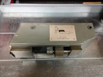
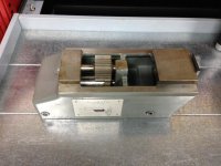
Here's some pictures of my FP1 riser, I can take some measurements if you need me too, just let me know.

IMG_1141.jpgIMG_1142.jpgIMG_1143.jpgIMG_1147.jpgIMG_1148.jpg

Kevin
 
Thank you bsg,

I could not see if there is an intermediate gear between the bottom and top gears on your FP1 riser. Can you confirm if there is one?

Alan
 
Thank you bsg,

I could not see if there is an intermediate gear between the bottom and top gears on your FP1 riser. Can you confirm if there is one?

Alan

Alan,

No intermediate gear, just the three gears pictured..... two on one shaft.

One would be the gear pitch for the FP1 and the second would be for the FP2 accessories.

I guess the riser is only meant for the late FP1's that can change the spindle direction?

Kevin
 
Well spotted Erik,

I`ve been spending some hours trawling through the old threads on the subject and found the riser 3D CAD drawings on the thread "FP1 riser drawings 01/21/2007.

I developed a headache after looking at many of the threads and had to take a rest. It seems that the riser is one of those subjects that rears it`s ugly head every so often and also noticed that the threads seem to fizzle out after a while without any positive outcome.

What I will do is to make a sketch based on bsg`s photos over the weekend and post it, so that we can add the actual dimensions to it.

bsg, Can you please add a photo of a side view of the riser that shows the protrusion of the gears above the top face.

Alan
 
Alan, I can see a problem with meshing. You can either make a mockup test riser with moveable gear(s), and when it's perfect,
make the correct riser with the input from the test model. Or just build the riser - making sure, you have some clearance between the gears.

After all, the height of the riser itself is not important. And then mill or grind the flats until the mesh is as good, as you can get it.

(I can see, why you asked only about the top. You already know the underside from your vertical head)

Or am I being stupid here? Is there an even easier way?

Cheers
Erik
 
Think if you have the tooth count for the gears and knowing the total height of the installed riser (105 mm factory) you should have most of the info you need.

Erik:
Don't think you can just grind the height to get the mesh you want....fits in dovetails on both sides....if you shorten the base side of a dovetail it becomes loose across the angled faces....
small changes Ok...but any real change might be problematic...


Cheers Ross
 
Whats the problem with dimensions ????
You have all you need
Remove the head From the top of your machine you can take the measurements for the top of your riser
From the bottomside of your head you can take the measurements for the bottemside of your riser
Then Ross provided you with this
Height of FP1 riser (net change) =105mm
Displacement of the mounted accessory = 25MM to the rear.

Ask BSG for a toothcount or figure out yourself what speed you want on the boring head
Thats basicly all you need

What I woud ad as a usefull feature is 2 gears at the top
1 with 15 dgr pressure angle and one with 20 dgr
so you could use it as a riser for the normal angle head with its 15 dgr PA and as a riser for the boring head with its 20dgr PA
The boring head is placed 25 mm backwards so it should be possible


Peter from Holland


Back
Top