AlfaGTA
Diamond
- Joined
- Dec 13, 2002
- Location
- Benicia California USA
Came across some old photos of my home FP2 this week, and although this has been posted years back and since the original photos are no longer view able,thought it might be fun to re-visit this......
Subject is the addition of a spindle brake for an FP2. Now the later machines have and electric brake on the main drive motor, the early (gen 1) machines have no such
setup. Now i could have added an electric setup i suppose, but i an more mechanically inclined, so i opted to build a full (almost) mechanical brake.
So here is how it all works.....The base for the setup lies in the actuator bracket....Basically i copied the original Deckel rapid /coolant switch mounting. Originally the factory
fit a shaft attached to a lever that operated a rod that applied pressure to the rapid clutch....
My setup employs that same setup fro the rapid lever, but i go a bit further in adding a second shaft (telescoping shaft within a shaft setup) , and this second shaft operates the brake....
That second shaft works a cam that operates a micro switch and is spring loaded to return the lever to its center position......Further the second shaft connects to a lever that operates the brake mechanism...
Also retained is the original setup using a center knob which operates the in/out clutch to drive the coolant pump....

Shafting made from pre-hard 4142 while the can (partially visible in the photo) was made from 17-4 PH and post heat treated....The housing carrying the spring is clearly seen as well as the three distinct
steps of the three shafts ( coolant, brake and rapid)
Following photo shows the general setup as installed on the machine....New shaft support bracket, operating rod for the rapid (angling down to the left) the operating lever for the coolant
(Just to the left of the bracket) and the round operating rod that operates the brake....(running up from the center toward the right ) Note the small rod ends on the rod to allow freedom for angular movement.

Also note the window cut into the machine casting at the top of the operating rod.....
To have a brake , you need some sort of shoe to do the work....Here is a shot of the brake shoe (one of 2) being cut out on my FP4NC.....
Material is mild steel.

Finished part, on holding fixture....(plate drilled and screws tapped into shoe through the plate)

Shoes were then sent to an automotive brake relining shop (i know guys) and friction material bonded to the shows....
Photo of installed brake assembly.....Mounts to a cast aluminum intermediate plate (original Deckel)
Assembly includes an anchor pivot pin and a cam (flat blade) that operates (opens) the shoes
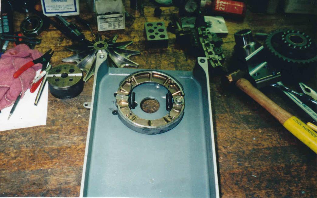
To the left in the photo you can see the end of the lever that is attached to the cam that opens the shoes....The return springs for the assembly
The hole centered with the shoes, is where the main drive shaft passes through into the machine's spindle gearbox.
More to follow....
Subject is the addition of a spindle brake for an FP2. Now the later machines have and electric brake on the main drive motor, the early (gen 1) machines have no such
setup. Now i could have added an electric setup i suppose, but i an more mechanically inclined, so i opted to build a full (almost) mechanical brake.
So here is how it all works.....The base for the setup lies in the actuator bracket....Basically i copied the original Deckel rapid /coolant switch mounting. Originally the factory
fit a shaft attached to a lever that operated a rod that applied pressure to the rapid clutch....
My setup employs that same setup fro the rapid lever, but i go a bit further in adding a second shaft (telescoping shaft within a shaft setup) , and this second shaft operates the brake....
That second shaft works a cam that operates a micro switch and is spring loaded to return the lever to its center position......Further the second shaft connects to a lever that operates the brake mechanism...
Also retained is the original setup using a center knob which operates the in/out clutch to drive the coolant pump....
Shafting made from pre-hard 4142 while the can (partially visible in the photo) was made from 17-4 PH and post heat treated....The housing carrying the spring is clearly seen as well as the three distinct
steps of the three shafts ( coolant, brake and rapid)
Following photo shows the general setup as installed on the machine....New shaft support bracket, operating rod for the rapid (angling down to the left) the operating lever for the coolant
(Just to the left of the bracket) and the round operating rod that operates the brake....(running up from the center toward the right ) Note the small rod ends on the rod to allow freedom for angular movement.
Also note the window cut into the machine casting at the top of the operating rod.....
To have a brake , you need some sort of shoe to do the work....Here is a shot of the brake shoe (one of 2) being cut out on my FP4NC.....
Material is mild steel.
Finished part, on holding fixture....(plate drilled and screws tapped into shoe through the plate)
Shoes were then sent to an automotive brake relining shop (i know guys) and friction material bonded to the shows....
Photo of installed brake assembly.....Mounts to a cast aluminum intermediate plate (original Deckel)
Assembly includes an anchor pivot pin and a cam (flat blade) that operates (opens) the shoes
To the left in the photo you can see the end of the lever that is attached to the cam that opens the shoes....The return springs for the assembly
The hole centered with the shoes, is where the main drive shaft passes through into the machine's spindle gearbox.
More to follow....


")
.jpg")
.jpg")
.jpg")
.jpg")