AlfaGTA
Diamond
- Joined
- Dec 13, 2002
- Location
- Benicia California USA
Doing a little project in the shop that i thought some here might find of interest....
Here is the problem:
Have a Ferrari 250"California Spyder" in the shop....initial problem is that the engine had low oil pressure. These engines rarely exhibit problems with oil pressure so the engine was removed from the chassis. A tear down and inspection revealed that the main and rod bearings ,while being worn, were within clearance specifications...
Looking further, it was discovered that the cam bearings were running well over .010" of clearance on the cam. Big clearance here = pressure loss
Bearings and caps had the appearance of having been worked over by hand, and not a nice job at that.....
So the cams were sent off for hard chrome on the journals and a reconditioning grind on the lobes. Size of the journals was raised from the nominal stock 25 mm to an oversize of: 25.25mm.
Both heads were straightened, then surfaced both top and bottom....Both heads made to the same overall thickness.
To repair the oversized cam bores the first step was to cut the head side of the cam bores.....Now i own a dedicated line boring machine...but the reality is that line boring a 25mm bore
over 610mm long is a total pain...and quite time consuming as the cuts must be by nature very small and light.....I have a different approach for this operation.
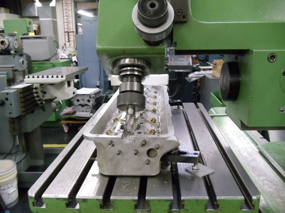
To re-pore the head side of the bearings, i used a ball end mill....Resharpened to the same size as the cam.
Photos show the operation. The vertical head of the FP4NC is angled....this is for several reasons....First off by tilting the cutter, i eliminate the dead cutting zone at the center of
the tool, and i get a better finish...
Second, the FP4NC does not have enough travel to cut the full length of the cam bearings in one setting...but by angling the vertical head to the right and cutting half of the head, then it is reversed and
angled to the left allowing the opposite side of the head and bearings to be cut.... The machine repeats well when doing the angle both right or left, so no issue on the setup as to accuracy of the cut.
The depth of the cut is gauged to keep the cam center line at the top surface of the cylinder head,and flat with same.
After milling, the head side on all journals (6) on each head, they are finish scraped to their individual cam.......The scraping gives clearance to the milled trough and corrects any small errors induced
by the milling setup.
So now i need to machine the mating part to finish the cam bearings....
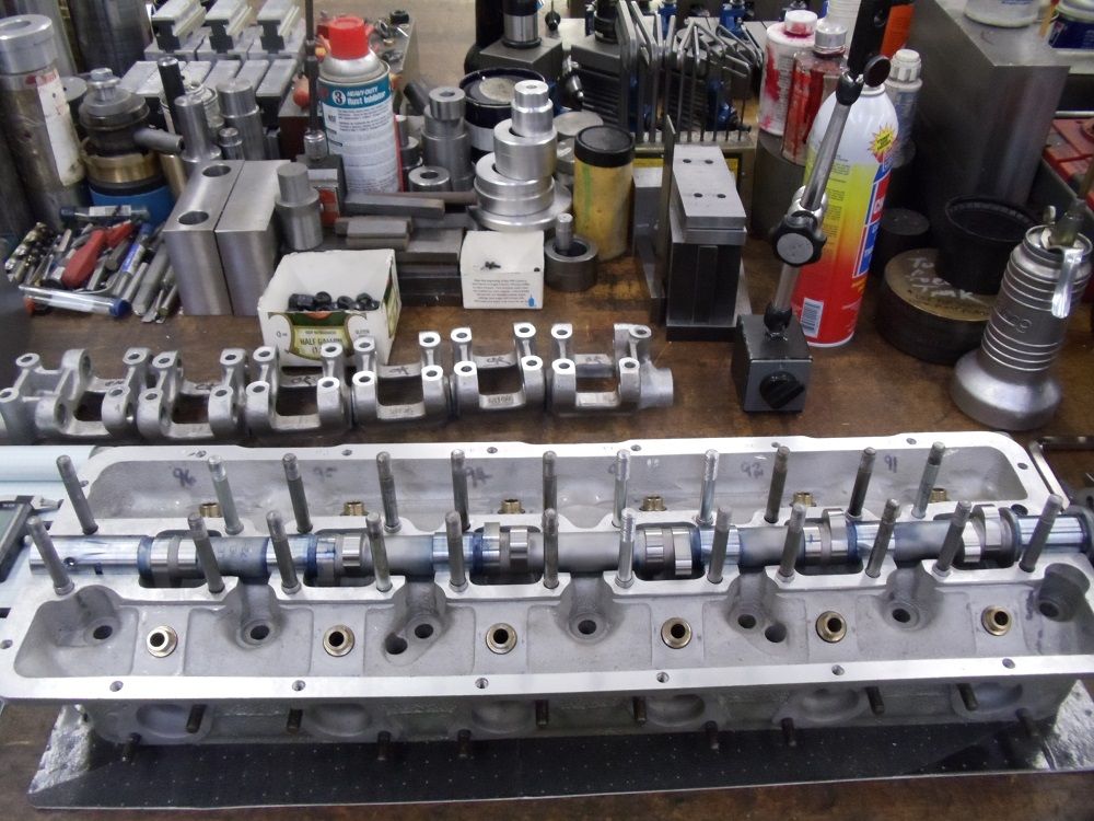
The arrangement for the head is that there are 6 cam rocker carriers and each carry two roller rockers that activate the valves for each cylinder (2 valve setup).....
That carrier also becomes the cam cap....The carrier is secured via 4-8mm studs with two ring dowels located diagonally at two of the studs.....
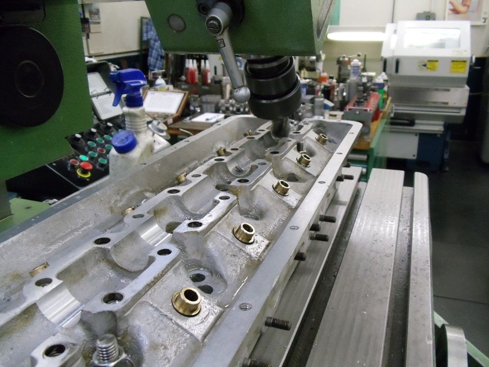
The second photo of the head being machined shows the stud holes (removed to gain access to the cam bearings) larger dowel holes and the cam bearings..
The cam is laid into the cylinder head, seating on the freshly scraped cam bearings. Carriers for the head are visible in the background of the below photo....
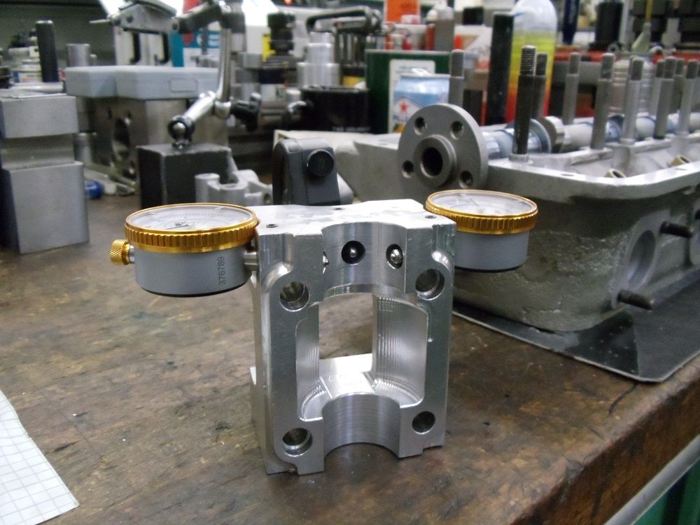
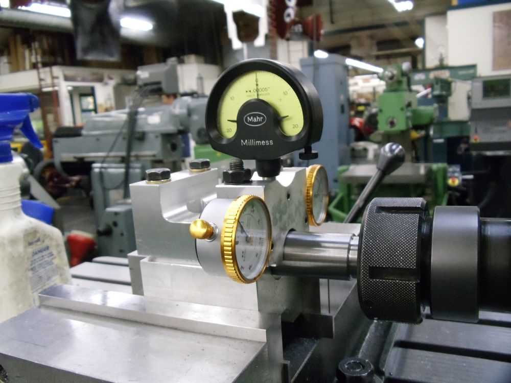
To use my process , there are three pieces of dedicated tooling needed.....
First off there is what i call the "dummy" cap....this is a piece of material that i have machined to replicate the cam carriers with bolt holes and dowel counter bores....
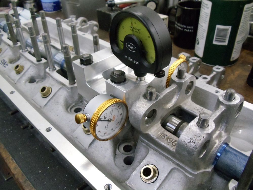
Further, it has the center relieved to allow clearance for the cam lobes, and has been machined for 3 indicators.....
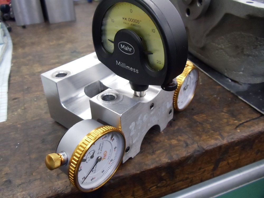
Indicators are placed so that the top one sits vertically to the cam and is positioned over the cam journal.....
The side indicators come in at an angle and point to the journal center line...and like the top indicator, are positioned over the journal of the cam.
Indicators are secured by set screws which allow some adjustment.....
More to follow.
Cheers Ross
Here is the problem:
Have a Ferrari 250"California Spyder" in the shop....initial problem is that the engine had low oil pressure. These engines rarely exhibit problems with oil pressure so the engine was removed from the chassis. A tear down and inspection revealed that the main and rod bearings ,while being worn, were within clearance specifications...
Looking further, it was discovered that the cam bearings were running well over .010" of clearance on the cam. Big clearance here = pressure loss
Bearings and caps had the appearance of having been worked over by hand, and not a nice job at that.....
So the cams were sent off for hard chrome on the journals and a reconditioning grind on the lobes. Size of the journals was raised from the nominal stock 25 mm to an oversize of: 25.25mm.
Both heads were straightened, then surfaced both top and bottom....Both heads made to the same overall thickness.
To repair the oversized cam bores the first step was to cut the head side of the cam bores.....Now i own a dedicated line boring machine...but the reality is that line boring a 25mm bore
over 610mm long is a total pain...and quite time consuming as the cuts must be by nature very small and light.....I have a different approach for this operation.
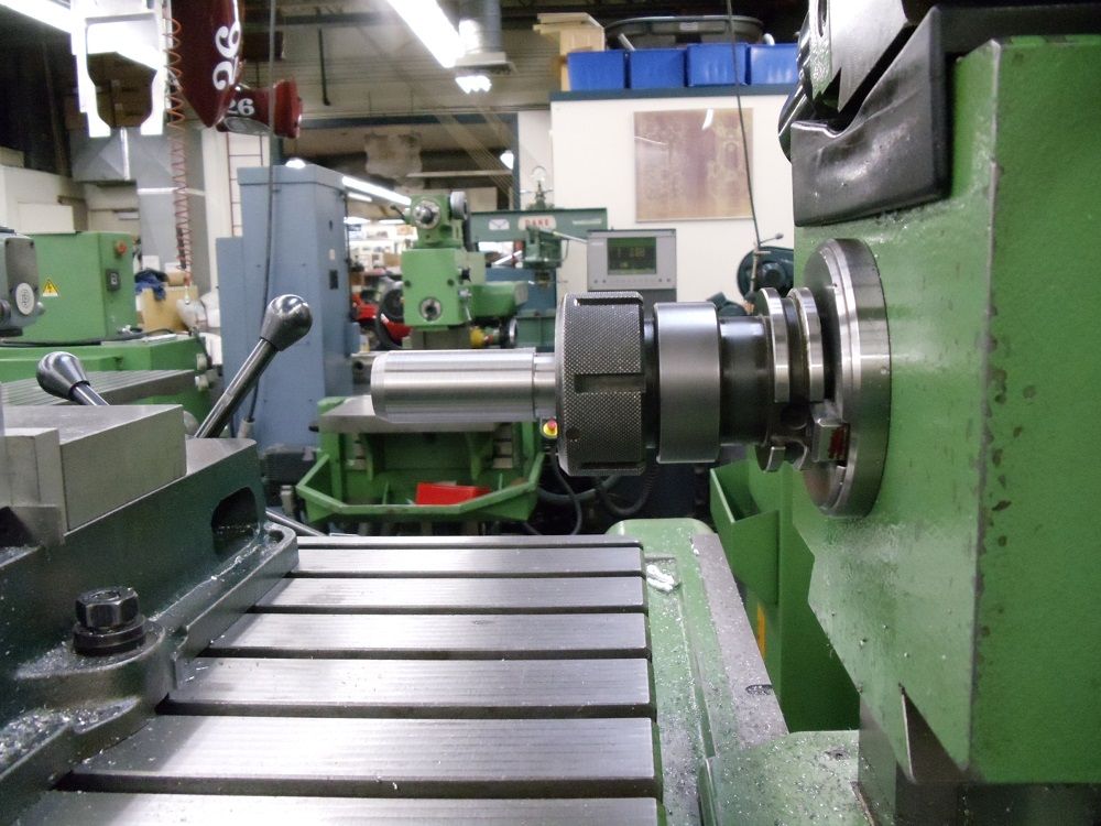
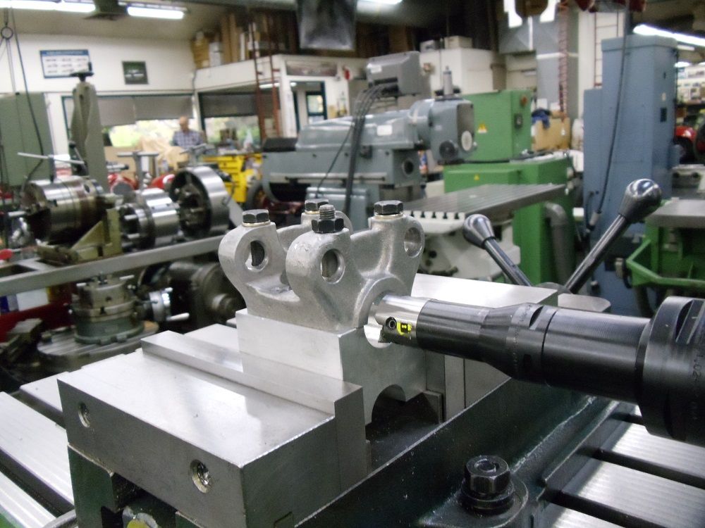
To re-pore the head side of the bearings, i used a ball end mill....Resharpened to the same size as the cam.
Photos show the operation. The vertical head of the FP4NC is angled....this is for several reasons....First off by tilting the cutter, i eliminate the dead cutting zone at the center of
the tool, and i get a better finish...
Second, the FP4NC does not have enough travel to cut the full length of the cam bearings in one setting...but by angling the vertical head to the right and cutting half of the head, then it is reversed and
angled to the left allowing the opposite side of the head and bearings to be cut.... The machine repeats well when doing the angle both right or left, so no issue on the setup as to accuracy of the cut.
The depth of the cut is gauged to keep the cam center line at the top surface of the cylinder head,and flat with same.
After milling, the head side on all journals (6) on each head, they are finish scraped to their individual cam.......The scraping gives clearance to the milled trough and corrects any small errors induced
by the milling setup.
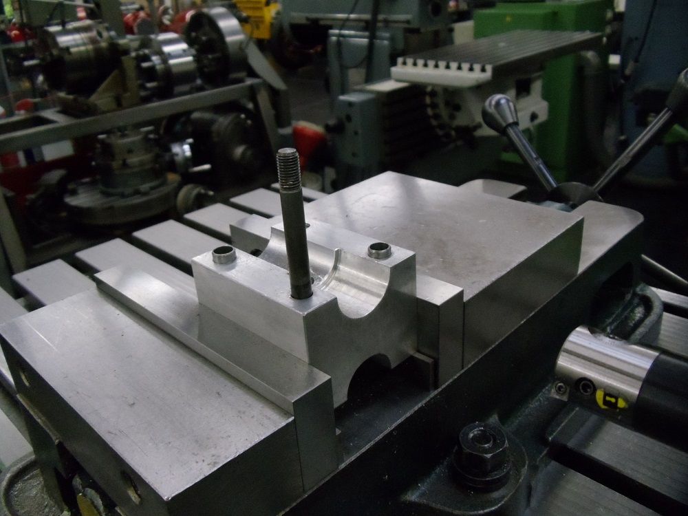
So now i need to machine the mating part to finish the cam bearings....
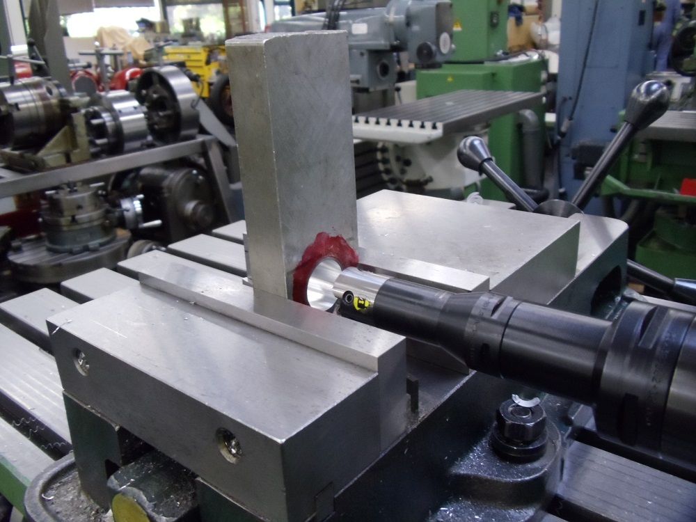
The arrangement for the head is that there are 6 cam rocker carriers and each carry two roller rockers that activate the valves for each cylinder (2 valve setup).....
That carrier also becomes the cam cap....The carrier is secured via 4-8mm studs with two ring dowels located diagonally at two of the studs.....
The second photo of the head being machined shows the stud holes (removed to gain access to the cam bearings) larger dowel holes and the cam bearings..
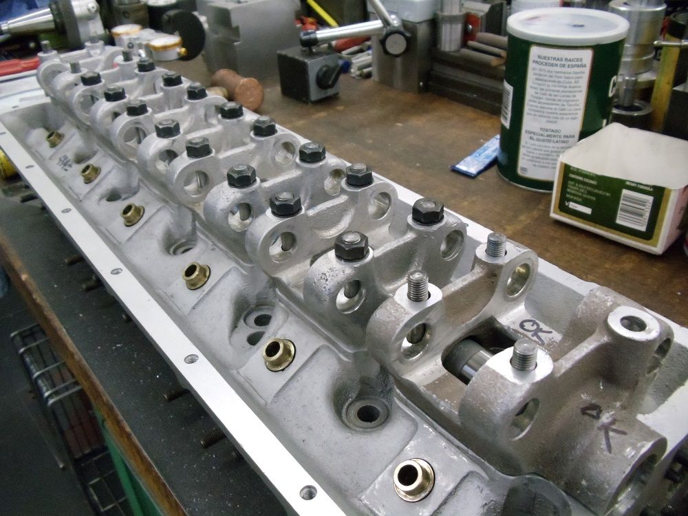
The cam is laid into the cylinder head, seating on the freshly scraped cam bearings. Carriers for the head are visible in the background of the below photo....
To use my process , there are three pieces of dedicated tooling needed.....
First off there is what i call the "dummy" cap....this is a piece of material that i have machined to replicate the cam carriers with bolt holes and dowel counter bores....
Further, it has the center relieved to allow clearance for the cam lobes, and has been machined for 3 indicators.....
Indicators are placed so that the top one sits vertically to the cam and is positioned over the cam journal.....
The side indicators come in at an angle and point to the journal center line...and like the top indicator, are positioned over the journal of the cam.
Indicators are secured by set screws which allow some adjustment.....
More to follow.
Cheers Ross
")
