What's new
What's new

Fitting DRO Scale to Aciera F5 X axis

rklopp

Diamond
Joined
Feb 27, 2001
Location
Redwood City, CA USA
I received the following PM from a member who can announce himself if he chooses. I feel the conversation should be public so it can help all of the other millions of Aciera F5 owners in the world :D.

"Hello Rich, as an owner of a F5 I have a question for you.

I am thinking of buying a late F5 (dc axis motor) and was wondering is there any way of mounting the X axis DRO scale under the table. I don't like the current side mounting as it sticks out the side of the machine way too much.
I know you can remove the X axis ruler assembly which would be my first job but re-fitting the scale may be a problem with the coolant tray directly below the table.
Having never actually seen an F5 I thought you may be able to help. Also any good tips to look out for would be helpful.
Many thanks"

My machine came with tapped holes in the lower corners of the "apron," and the tray detached. I think some prior owner had mounted an X-scale there, without the tray. The reader head appears to have been mounted on the face of the saddle at a place that would have been totally blocked by the chip tray. The red ovals in the photo below explain the situation. There were also tapped holes for what must have been a Y scale. I don't see any signs of a Z scale mounting, and whatever DRO was present was gone by the time I got the machine. I put on the chip tray, which came detached and may have been from another machine, and plugged the tapped holes with setscrews. I believe my machine is a late 1960s first generation F5, which has an identical apron and chip tray as my late 1970s F4.

Table.jpg

There does not appear to be enough room under the chip tray for an X scale when the Z is lowered to the bottom. In addition, I don't see an easy way to anchor the X scale to the apron and have the anchors poke through the chip tray. I supposed you could try to mount the X scale on the chip tray itself, but that seems like a terrible idea from a precision standpoint. Every single F4 or F5 X scale installation I have seen has mounted the scale on the trip dog spar for the X axis, and I have looked at dozens in photos. That is how I plan to mount mine when I get around to it. That is how the scale is mounted on my F4. In that case, the ruler function is gone, but the trip dogs are still functional. The left trip dog had surgery to clear the scale reader head cable, but it is still functional. The scale is fully contained within the length of the spar, so there is no more stick-out than the spar itself. I plan to keep both the ruler and trip dogs functional on my F5. Besides liking the trip dogs and scale, I will not remove the spar, because is has a lube Zerk fitting on it and helps to seal the place where the X feed screw and power feed shaft exit the saddle.

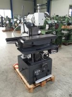
Here is a photo of a machine that I believe could be my machine's twin brother, as it shares some of the same tappings (including the end of the spar, which suggests my machine had a different DRO X axis installed at some point). The only difference is that my machine lacks the hand lever quill feed. Notably, the brother machine also is missing the chip tray. Both machines are Canadian.

s-l1601.jpg

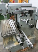
The following photo gives some idea how difficult it would be to mount the scale below the chip tray and have it anchored to the apron.

IMG_1836.jpg

I would google "Aciera F5" images, and see what others have done, and pick what you like.


There does not appear to be enough room under the chip tray for an X scale when the Z is lowered to the bottom. In addition, I don't see an easy way to anchor the X scale to the apron and have the anchors poke through the chip tray. I supposed you could try to mount the X scale on the chip tray itself, but that seems like a terrible idea from a precision standpoint.


Rich

Depending upon the chip tray's construction and how you'd do it, I wouldn't be afraid of that at all.

Judging from the pics, chip tray looks like it's made ouf ot cast aluminium? If so, the back side where it mounts on the machine is probably thick enough so as to give the whole thing some rigidity.
Plus everyone knows that such a chip tray invariably turns into a tool (or whatever) tray in no time, so I bet it would be more than suitable to hold a scale after the required machining.
Just see the tray as an intermediate part like the brackets one has to use to hold scales in numerous cases.

What is left is the room question. I must say that I have hard time figuring out the shape of the casting and the way the tray attaches to the machine.

You write that there doesn't seem to have room enough for a scale when the saddle is fully lowered, wich is not obvious from the pics.

Could you post a pic of the back of the tray ?

I had a similar experience quite recently with a Schaublin 13, wich turned out to be the worst machine I had to fit a DRO on.
The installation of the x axis scale was really horrible. I had to machine the carriage, and redo a good part of the trip dogs system, so as to be able to fit the scale without sacrifying it.

My search on the internet gave me good examples of what NOT to do, but was pretty useless in the end...
 
T
I am quite certain an X DRO scale cannot work mounted below the chip tray. The following photo shows where it would have to go, as indicated by the dashed line, but it would not clear the vertical hand wheel shaft support (the large round part to the left of the Zerk lube fitting). In addition, the gray painted surface is well forward of the apron face above. The two planed surfaces to the rear above the dashed are totally obscured by the chip tray. The chip tray slides past both surfaces in close proximity, and the coolant return occupies the rear portion of the horizontal planed surface.

I am in an airport, and not able to see how much clearance there is between the underside of the chip tray and the top of the base casting when the saddle is at Z max. I don t think there's much.

The X spar was designed for measuring equipment, like the ruler and even gauge blocks and an indicator, so it is a natural spot for a DRO scale.

Table copy.jpg

Klopp
 
I notice the F4 has the X spar on the left hand side but the F5 has it on the right.

May be it's not an issue on the smaller machines with 400mm of X travel, however the late F5 is
larger with 500mm of X travel. This means the spar is sticking out by about 700mm.
A Heidenhain scale assuming it's a minimum ML520 is 630mm long.

It does seem odd poking out the side where you stand and operate the machine,
but at least the limit dogs are far more accessible than a Deckel.

Ciao Adrian.
 

Attachments

  • Aciera F4.JPG
    Aciera F4.JPG
    97.5 KB · Views: 210
  • Aciera F5-8.jpg
    Aciera F5-8.jpg
    58.3 KB · Views: 197
Here is the scene under the chip tray. I suppose you could squeeze in a Newall Microsyn tubular scale under the chip tray and above the hand wheel housing, but the accuracy would depend on the chip tray stiffness and would be a very long way from the slide where the motion actually occurs. The chip tray is bolted to the bottoms of the apron leadscrew bearing housings at each side. IMHO it is not sufficiently structural for mounting a DRO. It is a nicely made aluminum casting, but is designed to catch chips and coolant (and tools), and not follow rigidly with the apron motion.

IMG_2433.jpgIMG_2434.jpg

As for the spar being in the way, I find that is not the case. My machine does not nave a hand crank on X, only a wheel, so most moves beyond a fraction of a turn are done with power feed or rapid. Most of the time, the X hand wheel sticks out the same as the spar, and no differently than a Deckel or Maho.
 
Apart from being very close to the handwheel, it looks a perfect height to catch your man tackle when standing at the side of the machine.

I wonder why they moved it from the left.

Ciao Adrian.
 
I wonder why they moved it from the left.

Good question. No idea. Another question I have wondered about is, why is the F3 operator position on the opposite side of the column compared to the F1, F2, F4, and F5?

The F5's spar is at or above my waist most of the time. It is more of a threat to one's iliac crest than to nuts.
 
As for the spar being in the way, I find that is not the case. My machine does not nave a hand crank on X, only a wheel, so most moves beyond a fraction of a turn are done with power feed or rapid. Most of the time, the X hand wheel sticks out the same as the spar, and no differently than a Deckel or Maho.

Is your machine different from the photos posted by Adrian? That machine appears to have lots of overhang to my eye...

Cheers Ross
 
Is your machine different from the photos posted by Adrian? That machine appears to have lots of overhang to my eye...

Cheers Ross

The photo Adrian posted magnified the spar using a wide-angle lens. My machine is older, having a shallower chip tray and no hand cranks. The F4 picture he posted has more realistic perspective. Just flip the spar to the other side on the F5.

By the way, the F4 and F5 are friendlier* to operation from the front position compared to a manual Deckel, so whacking into the spar is not much of an issue.

* I admit the Y hand wheel on the F5 is a bit awkward from the front, but you get used to it, plus I drive mostly with power feed and rapids. There is little reason to want to drive an F4 from the side.
 
No doubt that if the spar is to be kept (I'd keep it), it is probably the most convenient location for the x-axis scale.

But man ! What a weird layout !!!
I bet such a setup would have brought lots of laughs and mockery if shown by a hobbyist.
How the factory did not come up with a sleeker design is surprising to say the least.

But I suppose this is the typical situation where one has to see and use the real thing "in flesh" to get a proper feel about it.
 
Unfortunately the image I chose does makes it look exaggerated, but from the front it still looks odd.

Having never seen or operated the larger F5 in the flesh it's difficult to make a call on the subject.
However it looks a really nice machine and at the end of the day most machines have their own little annoyances or would it not be nice feature.

Ciao Adrian
 

Attachments

  • Aciera F5-3.jpg
    Aciera F5-3.jpg
    56 KB · Views: 132
But man ! What a weird layout !!!
I bet such a setup would have brought lots of laughs and mockery if shown by a hobbyist.
How the factory did not come up with a sleeker design is surprising to say the least.

Putting the scale inside the table would surely have been a better design. But probably the design of the machine and the castings was done before the time (or around the time) that DROs first became widely available at reasonable cost. So the "spar" was the practical "solution". This might have looked better to the designers of those days because the location was also the same as the location where a tray for gage blocks would have been placed.
 
Putting the scale inside the table would surely have been a better design.

The tables on these machines are moveable and can be interchanged among fixed, tilting, vertical, lowered, and coordinate/dividing, so putting the scales in the table would have been impractical. Maybe Aciera could have squeezed a scale into the apron. However, the apron was designed in the 1950s for the first generation F4 and seems to have been carried over to the F5 in the late 1960s.
 
Rich:
Think that Bruce is talking about the vertical table....not the work table...

As an example, starting with the FP3's Deckel managed to place the "X" axis scale inside the "X" axis slide/vertical table ....sort of like the later FP-NC's.
No interference with travel, trip stops and hidden out of the way.

Think the FP1's got that treatment later owing to their small size.
Cheers Ross
 
As an example, starting with the FP3's Deckel managed to place the "X" axis scale inside the "X" axis slide/vertical table ....sort of like the later FP-NC's.
No interference with travel, trip stops and hidden out of the way.

Think the FP1's got that treatment later owing to their small size.

Ross
It never happened on the FP1, even on the latest models.

In the end, the factory just got rid of the trip stops system.
Here are a couple of shots of the saddle and carriage of an aktiv three axis machines where one can see the recessed pocket milled for the x-axis reader bracket, and the tapped holes for the scale.
The T-slot for the stops completely disappered.

Deckel FP1 Aktiv montage des règles Heidenhain (13).jpg Deckel FP1 Aktiv montage des règles Heidenhain (7).jpg
 
T:
Thanks for that info.....Only owned one FP1 over the years. That was an early version that had change gears for the feed...(1942 i think)
Gave that machine away to a fellow worker...for a house warming present....

Looks like the "T" slot for the stops is not the only thing that has disappeared..Looks like the scraping is also pretty well missing...:stirthepot:

Cheers Ross
 
Yes... No hangar queen here.
I've had (and still have) my share of beaters !
But curiously, some of them are the machines I had the most joy to play with.


Back
Top