AlfaGTA
Diamond
- Joined
- Dec 13, 2002
- Location
- Benicia California USA
It has been some time since i posted about the rebuild of my FP3NC "flip head".
I have been working pretty steady since the last posting....mostly after work in the evenings i can work in an hour or two.
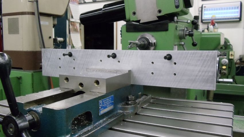
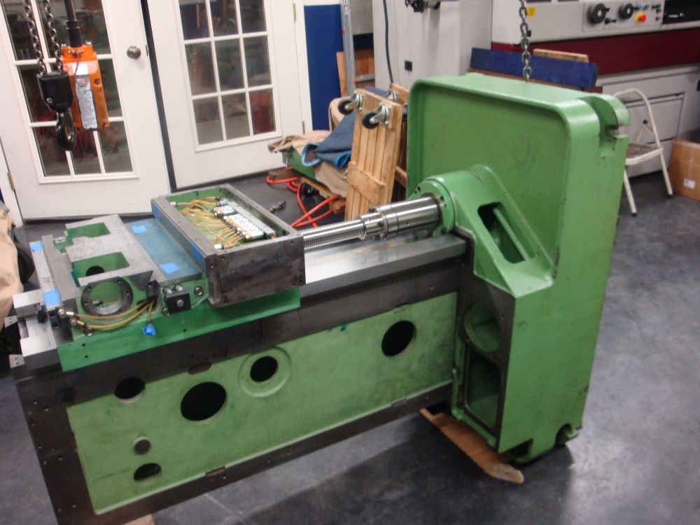
At last posting i was working at mating and aligning the vertical slide to the side ways of the freshly reground main vertical casting.
The object was to scrape the inside faces of the vertical casting "Boxes" to get the table to move as close to perpendicular to the vertical box as possible.
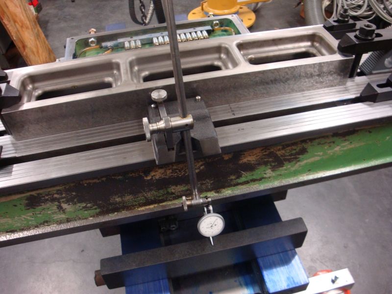
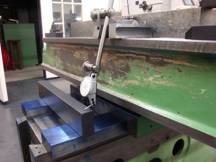
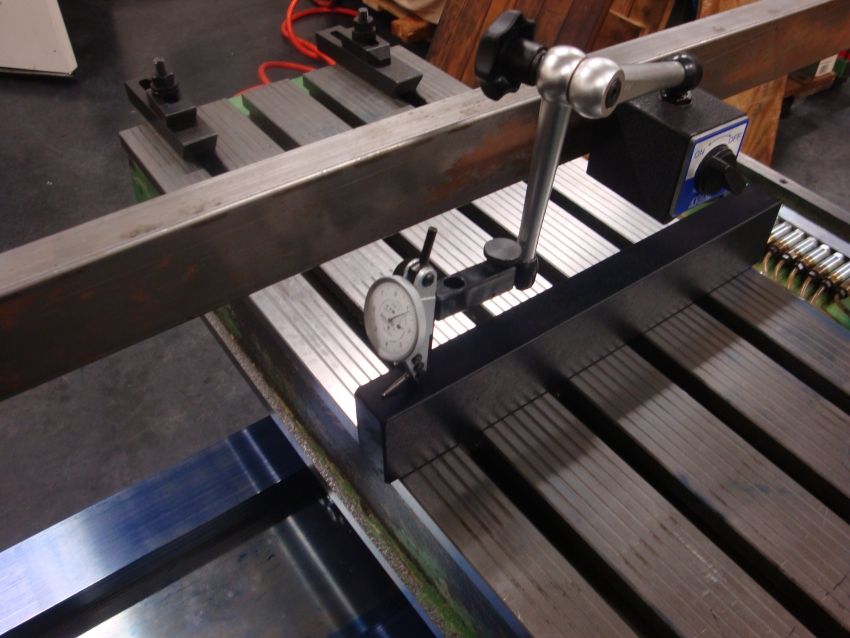
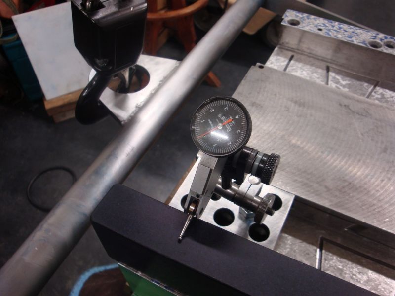
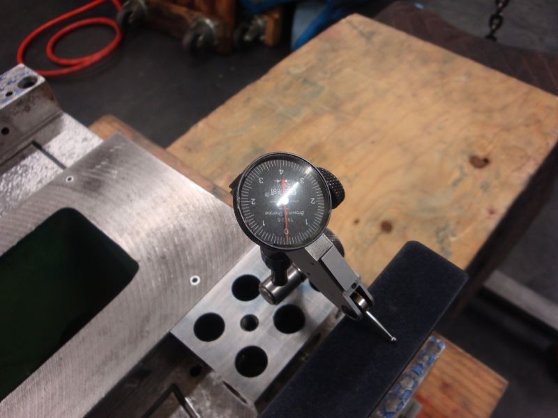
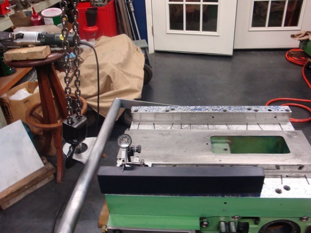
My gauging method is to fit a qualified granite square to the table face...align one face to indicate true with the table move "X". Then check at 90* on the granite
by moving the vertical slide along the box ways.
Some disclaimers...I have been questioned about my method..that is the main casting is laying down and presenting the box ways up. I know about the effects of gravity and
potential casting sag. Because i need to be able to fit the table and move it from side to side for one of the tests, i needed a way to keep the main casting from turning over
with the weight shift of the table move. I fitted support legs at one end of the main casting with bolts fit to the original base mounting locations. The opposite end of the main casting (about 2/3 the way up) is a second support or leg...this one is not secured to the casting, so some float is possible. For this work a true 3 point support is just not possible.
I have looked at the main casting using a qualified straight edge while on 3 points...and again supported in the manner i am using with the mounting feet bolted to one end...i can't detect any difference in the blued pattern either way.....
So i got the side of the boxes and the movement of the table pretty much where i it is as good as i dare...figuring i could easily make it worse trying to get the last tenth.
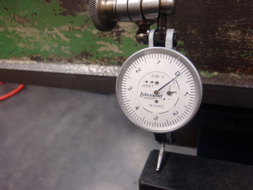
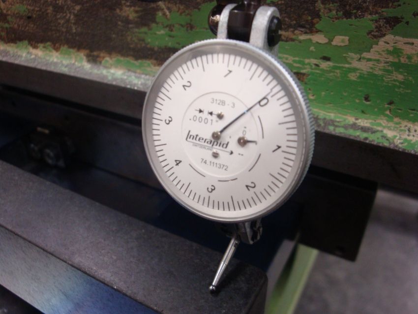
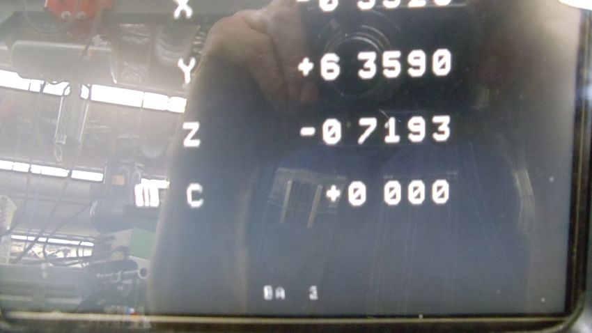
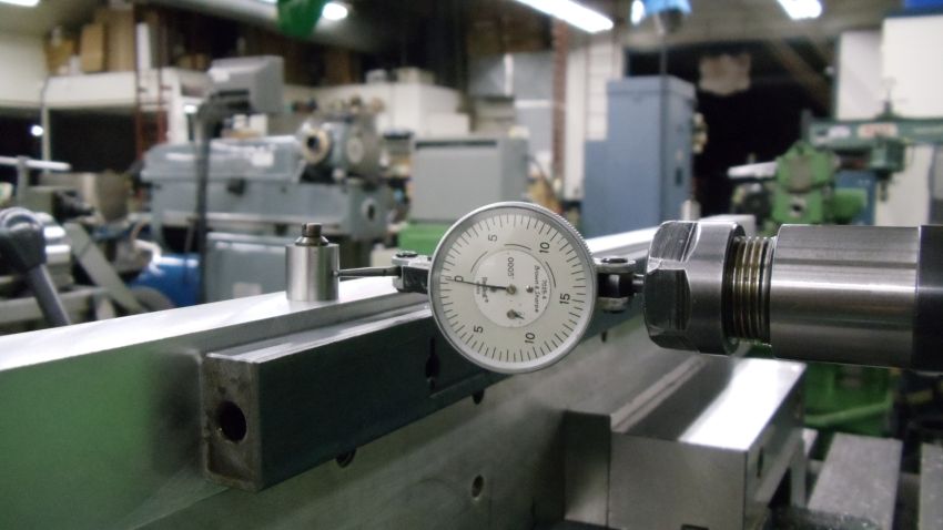
Currently as best i can test the vertical move is within .0001" of total error in 14" of movement, when the table move (X) clocks at 0.0000 (by my trusted tenths reading Interapid
indicator. (purchased new for this job)
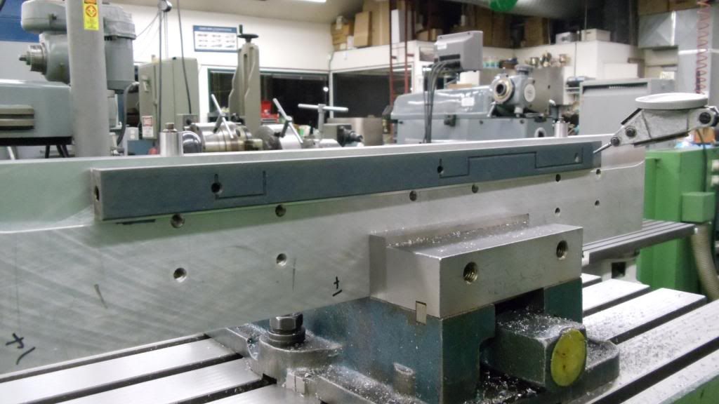
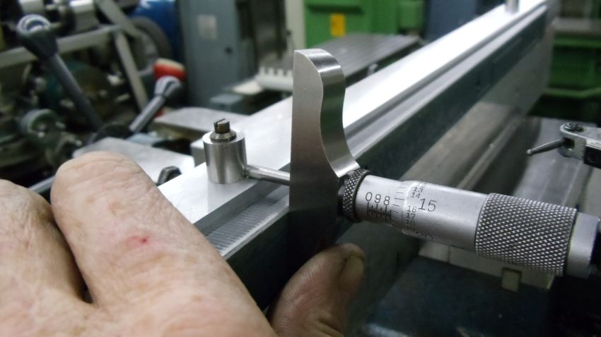
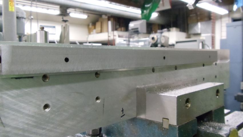
Next part of the fitting puzzle was the floor or face of the main vertical box ways on the vertical slide. I was looking for two checks here.
First i wanted the face of the table when fit to the vertical slide to be flat (in the X plane) with both faces of the reground box ways on the face of the main casting.
Further i wanted the table face in the "Z" plane to be tipped somewhat in at the top compared to the bottom. This is because i believe the entire assembly when standing
upright will have a tendency to tip forward from clearance in the back keeper gibs on the vertical slide and and the clearance of the upper keeper gib on the back of "X" axis table....
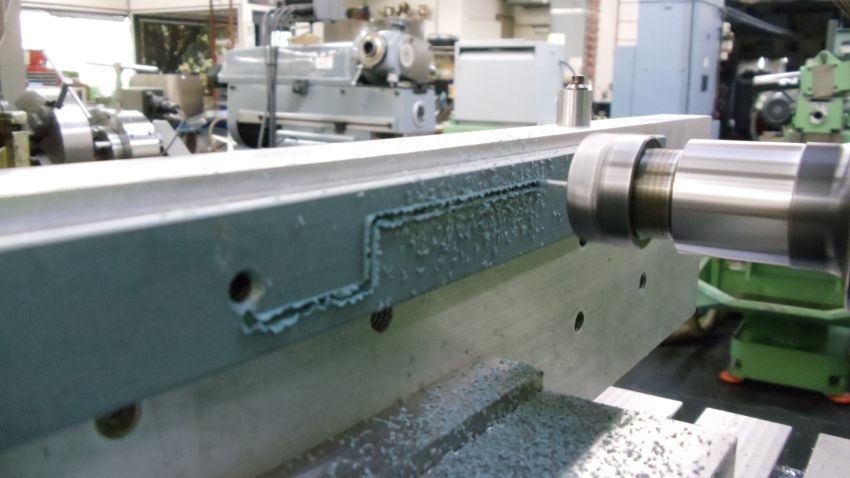
The scraping of the box way presented some problems for me. Normally when scraping you alternate your scraping strokes at opposite angles. Creating a criss cross cutting action alternating the direction with each scraping cycle. This generates the spots that form the bearing surface.
However working with the scraper in a sort of trough it became impossible (at least for me) to get a good angled cut. the scraper was kept from being able to cut across the entire surface due to the overhang of sorts caused by the sides of casting.
I could get good cross pattern at the ends, but not very far up into the slot. As a result most of the cutting was done a relatively shallow angles...somewhat parallel with the long axis of the surface. The resulting pattern on the surface tended to have somewhat longer islands or spots.
In my shop lifting is done (until i get my crane finish) using an electric hoist slung from a central beam across the shop.
I needed a better way to manipulate the vertical casting between marking off the reground ways and scraping.
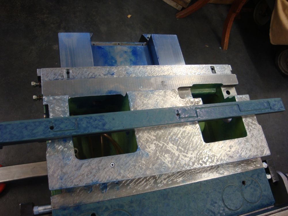
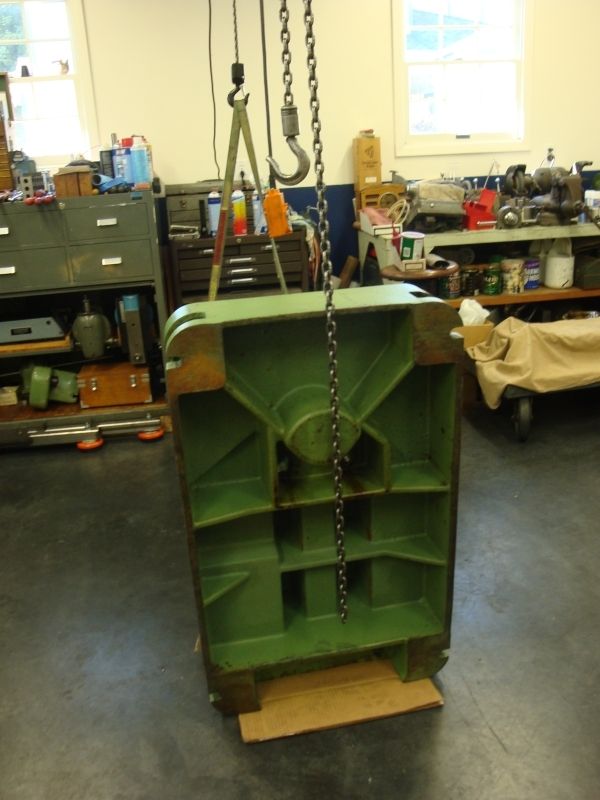
What i came up with is a sort of roll over fixture.
Mounted to the sides of the vertical casting with plates at a point where the casting balanced. There are pivots connected to a cross frame that allows rolling the casting over with almost no effort.
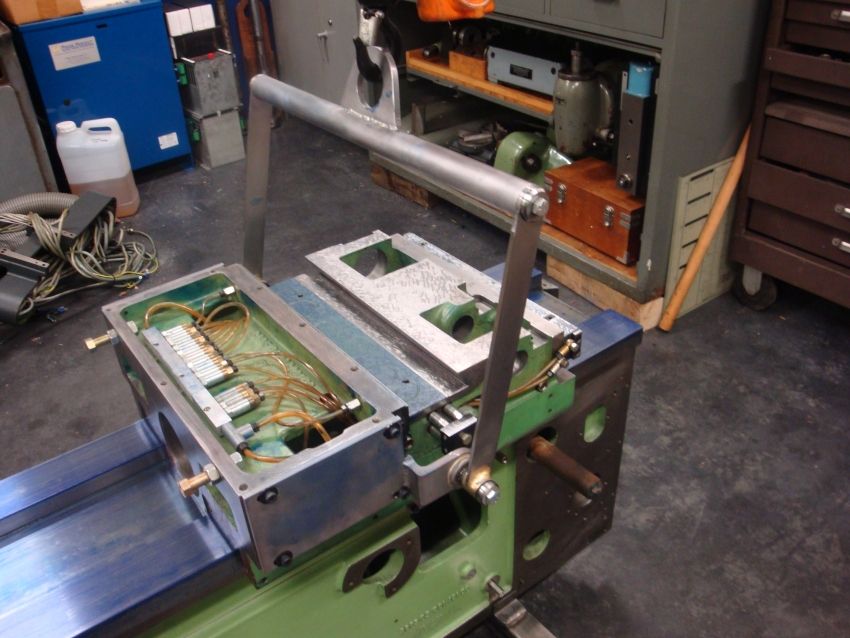
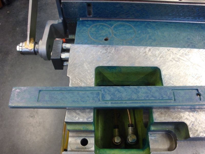
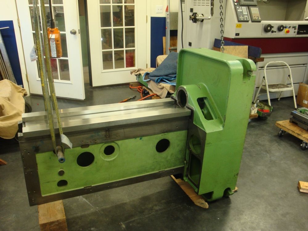
Here is the fixture and the vertical casting in position to take a print. Blue applied to the box way face and the casting lowered to make contact.
Additional benefit here is the ease of setting the casting down on the way face....because the vertical slide can be tipped, it is easy to tip one end to make contact and slip into alignment
without using the movement (kind of rapid for this) of the crane. Once the parts are aligned and started then the crane is used t complete the down move....
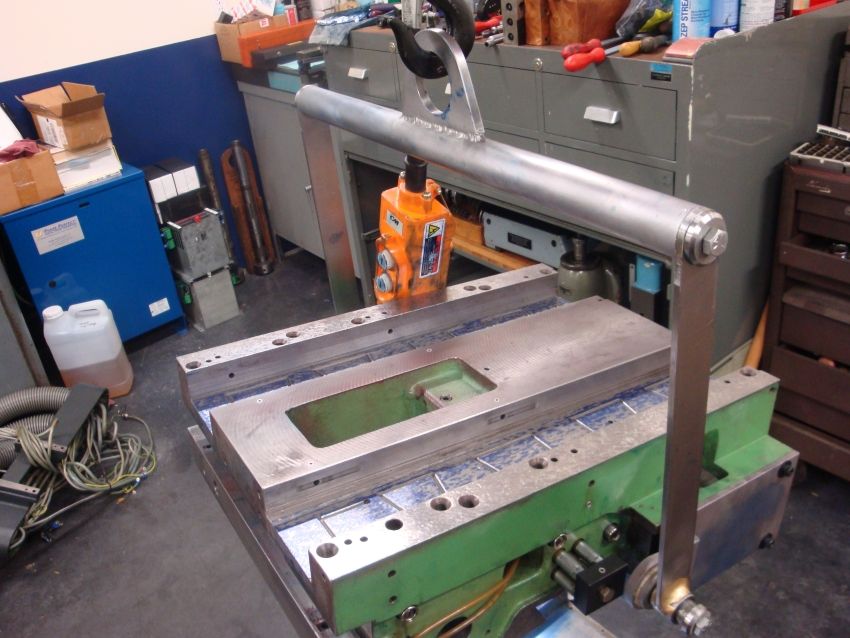
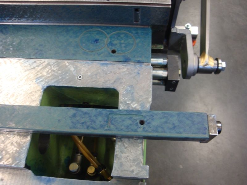
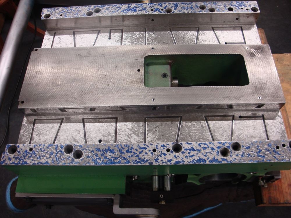
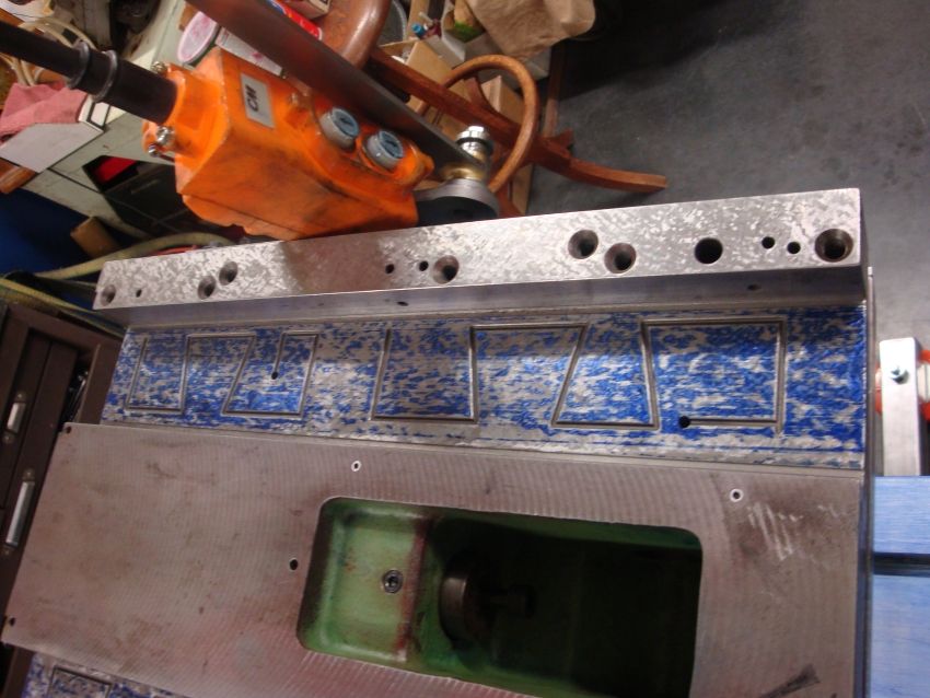
Here the vertical slide has been rolled over and the "print" can be seen.
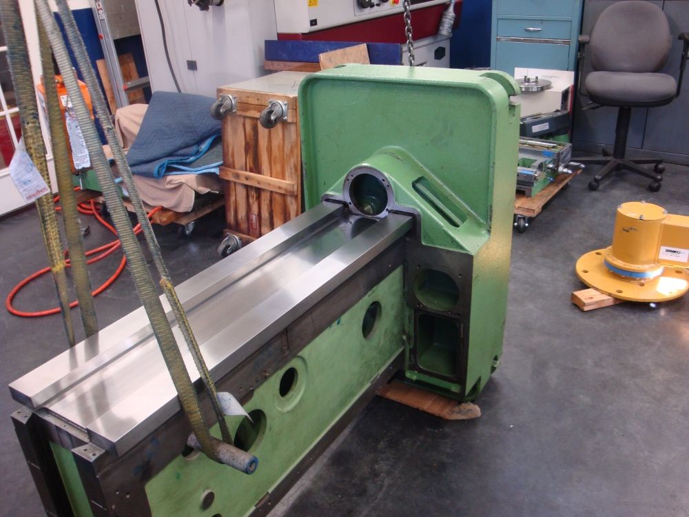
To do the scraping on the marked surface, i place a moving blanket over the main casting face then a piece of plywood on top of that.
Then the vertical slide is lowered to the ply...Makes a nice bench where the scraping can be done and the only action to do a cycle is lifting the vertical slide......
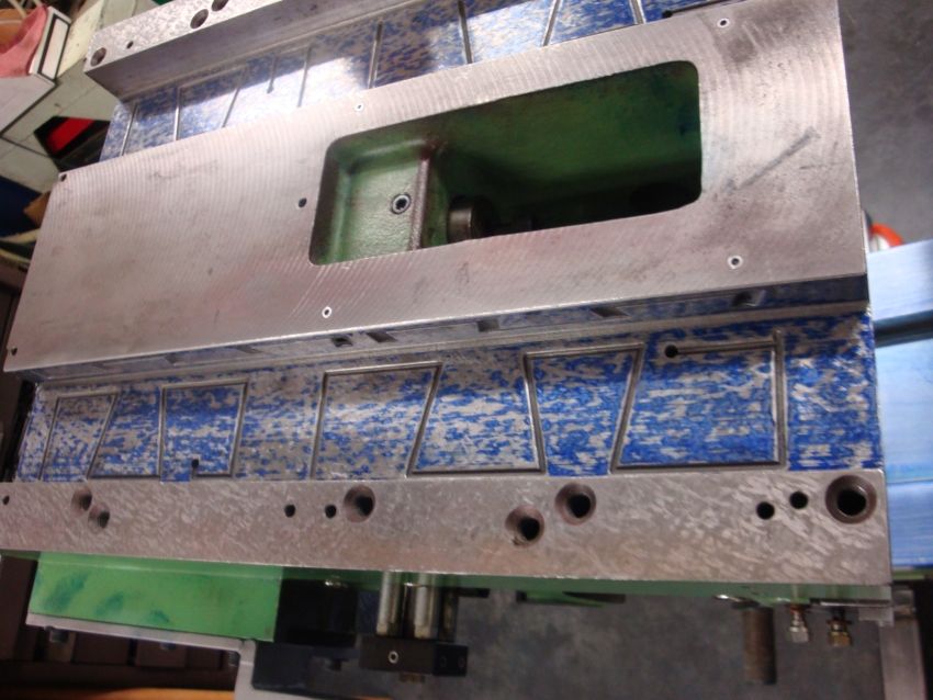
Here you can see the casting set down ready to be scraped...
Non marked area in the center is by design....I scraped until i had a pattern on the entire surface, then made two additional cycles to relieve the center area...this
is done i am advised to prevent the parts from tipping and rocking as they wear.
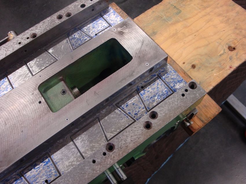
Surface before relieving
More to follow.....
Cheers Ross
I have been working pretty steady since the last posting....mostly after work in the evenings i can work in an hour or two.
At last posting i was working at mating and aligning the vertical slide to the side ways of the freshly reground main vertical casting.
The object was to scrape the inside faces of the vertical casting "Boxes" to get the table to move as close to perpendicular to the vertical box as possible.
My gauging method is to fit a qualified granite square to the table face...align one face to indicate true with the table move "X". Then check at 90* on the granite
by moving the vertical slide along the box ways.
Some disclaimers...I have been questioned about my method..that is the main casting is laying down and presenting the box ways up. I know about the effects of gravity and
potential casting sag. Because i need to be able to fit the table and move it from side to side for one of the tests, i needed a way to keep the main casting from turning over
with the weight shift of the table move. I fitted support legs at one end of the main casting with bolts fit to the original base mounting locations. The opposite end of the main casting (about 2/3 the way up) is a second support or leg...this one is not secured to the casting, so some float is possible. For this work a true 3 point support is just not possible.
I have looked at the main casting using a qualified straight edge while on 3 points...and again supported in the manner i am using with the mounting feet bolted to one end...i can't detect any difference in the blued pattern either way.....
So i got the side of the boxes and the movement of the table pretty much where i it is as good as i dare...figuring i could easily make it worse trying to get the last tenth.
Currently as best i can test the vertical move is within .0001" of total error in 14" of movement, when the table move (X) clocks at 0.0000 (by my trusted tenths reading Interapid
indicator. (purchased new for this job)
Next part of the fitting puzzle was the floor or face of the main vertical box ways on the vertical slide. I was looking for two checks here.
First i wanted the face of the table when fit to the vertical slide to be flat (in the X plane) with both faces of the reground box ways on the face of the main casting.
Further i wanted the table face in the "Z" plane to be tipped somewhat in at the top compared to the bottom. This is because i believe the entire assembly when standing
upright will have a tendency to tip forward from clearance in the back keeper gibs on the vertical slide and and the clearance of the upper keeper gib on the back of "X" axis table....
The scraping of the box way presented some problems for me. Normally when scraping you alternate your scraping strokes at opposite angles. Creating a criss cross cutting action alternating the direction with each scraping cycle. This generates the spots that form the bearing surface.
However working with the scraper in a sort of trough it became impossible (at least for me) to get a good angled cut. the scraper was kept from being able to cut across the entire surface due to the overhang of sorts caused by the sides of casting.
I could get good cross pattern at the ends, but not very far up into the slot. As a result most of the cutting was done a relatively shallow angles...somewhat parallel with the long axis of the surface. The resulting pattern on the surface tended to have somewhat longer islands or spots.
In my shop lifting is done (until i get my crane finish) using an electric hoist slung from a central beam across the shop.
I needed a better way to manipulate the vertical casting between marking off the reground ways and scraping.
What i came up with is a sort of roll over fixture.
Mounted to the sides of the vertical casting with plates at a point where the casting balanced. There are pivots connected to a cross frame that allows rolling the casting over with almost no effort.
Here is the fixture and the vertical casting in position to take a print. Blue applied to the box way face and the casting lowered to make contact.
Additional benefit here is the ease of setting the casting down on the way face....because the vertical slide can be tipped, it is easy to tip one end to make contact and slip into alignment
without using the movement (kind of rapid for this) of the crane. Once the parts are aligned and started then the crane is used t complete the down move....
Here the vertical slide has been rolled over and the "print" can be seen.
To do the scraping on the marked surface, i place a moving blanket over the main casting face then a piece of plywood on top of that.
Then the vertical slide is lowered to the ply...Makes a nice bench where the scraping can be done and the only action to do a cycle is lifting the vertical slide......
Here you can see the casting set down ready to be scraped...
Non marked area in the center is by design....I scraped until i had a pattern on the entire surface, then made two additional cycles to relieve the center area...this
is done i am advised to prevent the parts from tipping and rocking as they wear.
Surface before relieving
More to follow.....
Cheers Ross