What's new
What's new

How do I remove the FP1 slow feed drive and X axis feed direction change parts

bentley1930

Hot Rolled
Joined
Mar 30, 2015
Location
norway oslo
Hi All,
I`ve stripped down my FP1 into large lumps and this has toned up my aged muscles no end!
In a previous thread where I asked for information about how to identify the parts that were missing from my slow feed system, I jumped through all the hoops and shelled out on Alan`s DVD but the info that I needed was not there on the parts lists as these did not show the operating mechanism clearly enough and gave no part numbers either.
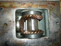
I think that I`ve found the root of the problem on the lack of slow feeds the reason being that the drive to the X axis slow feed has seized up in the saddle casting and as I can`t rotate the bevel driving gear I cannot drive out the pin to release it.
Can anyone give me some advice as to how to remove these parts from the saddle?
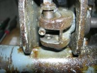
I enclose some photos to show the state of affairs. the first two show the empty space where the change X axis direction parts should be.

DSCN2426.jpgDSCN2427.jpgDSCN2437.jpgDSCN2438.jpgDSCN2439.jpg

The last photo shows that there is a part missing from the gear lever lower end.
Alan
 
The first question that comes to mind is : "how hard are the bevel gears seized", because IIRC, those are steel gears supposed to spin in bronze bushings so it seems pretty unlikely that they would be seized that hard.
The internals of your machine seem pretty clean. Comparable to most of what I've encountered so far, with limited corrosion.

You can try to rotate the gears using the feed bar and the drivetrain mechanism, or if you don't want to stress the other components, machine a dedicated tool to mimic the leadscrew for its slotted part, and actuate the bevel gears from the opposite siden of the screw bronze nut.
That way, I suppose you could apply a fair amount of torque without fearing to bend anything and I'd be surprised if you could not rotate the gears so as to get access the big end of the tapered pin.

Anyway, you don't have much choice, as there's no other way to remove those gears than to extract the pin.

Those pins can be a nightmare to remove though. In my experience, the best method is to show them who's the boss from the get to.
I mean spray the pin area generously with penetrating oil, use a good pin driver in good condition and a mash hammer, and act as if you had only ONE try.

In the past, I used to be a little shy on my first tries, wich would always end up in distorded pin ends and then hours of "negociation" with the latters... Seems to me that since I took the habit of smashing the pin to be removed as hard as I can from the very first stroke, I'm much more successfull.

That's for freeing the upper bevel gears but as you probably noticed, the dismantling of the whole mechanism begins from the bottom of the saddle if you want to remove the parts !
 
Hi TNB,
Actually the gears do look as though they are bronze! At the moment it`s "spray and pray" as I`ve applied a liberal amount of WD40 to the bevel area where they enter the saddle.
As I said The drawings that I looked at were such a small scale that I was unable to determine how the assembly could be dismantled and I didn`t want to apply too much brute force. I will probably drill out the pin and shear off the little of the pin that remains by force on applied at the shaft.
What happens when I manage to remove the shaft and the small bevel gear?
Do you live near 16700 Ruffec?
Alan
 
Hi Alan,

I am not sure about this, but it might be possible to remove the shafting from INSIDE the bevel gears first. See the corresponding steps for an FP2, starting here. If that is possible, I would do it.

If that is not possible, then as I recall, the shifting for X (left - off - right) is accomplished via the internal splined shaft, which can be in the left/center/right position. From your photos, it appears to be in the "off" center position, but I am not sure. It is possible that the gears are free to spin, but that this splined shaft/clutch is in the left or right rather than center position, and does not turn easily?

To check this, see if you can rotate that center splined shaft. You will need to reinsert the lead-screw and key.

If that works, then I would try as TNB suggests, to rotate the power feed shaft.

Another thing to try: you could (a) reinstall the X shift mechanism (b) insert the lead-screw and key (c) engage the clutch for left or right and (d) apply rotational force to the lead screw. This will then (via the spline shaft) try to rotate one or the other of the X bevel gears. If one of them is frozen, you will see it here, because you will be able to wiggle/jiggle one gear but not the other.

Next suggestion: WD-40 gets its name from "Water Displacement". It is for getting rid of water to prevent rust. You should use a "real" penetrating lubricant that dissolves rust and corrosion and has very low viscosity. I'm not sure what brands are available in Norway, but someone here can surely suggest something appropriate. Keep applying it.

Be patient, don't force, keep wiggling the parts and thinking about what is wrong, and you will figure this out and fix it. This is a problem for brains not muscles (fortunately aging brains work better than the aging muscles!) Once you get one of those two gears to wiggle even a little bit one way or the other, you can be pretty sure that you will win the battle!

Good luck,

Cheers,
Bruce
 
Bill,

You`re a hero!
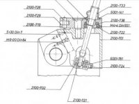
Did you take dimensions of the X axis selector shaft and lever assembly? As this is what`s missing from my machine.

FP1 X axis change lever.jpg

I didn`t quite understand your method of extracting the internal shafts. do you extract the left hand part from the left hand side of the saddle and then extract the right hand part from the right hand end of the saddle?
can the whole shaft assembly be extracted together and can this be done with the bevels in place?

FP1 X axis change direction extraction.jpg

Can someone tell me how to enlarge the posted photos after you have selected them and they are on the screen?

Alan
 
Bruce,
You sent your post while I was writing mine! I will try re-inserting the leadscrew as you kindly suggest. One of the bevels is rotatind slightly so that I may have some luck.
My leadscrew nut is very worn but the thread on the leadscrew is in quite good condition and only varies a few thou along it`s length. I was going to sleeve the nut and recut the internal thread as bill suggested, but probably will further fill the overflowing coffers of uncle Franz by buying one of his new ones.
On the Singer website he offers to recondition an FP1/2 leadscrew plus nut in exchange for your existing leadscrew plus Euro 1200 plus postage plus VAT.
The nut alone costs Euro 156 if I remember correctly.
Alan
 
Last edited:
Hi Alan,

- I revised my post a bit, so please read it again. I would start by trying to REMOVE the splined shaft. Follow the link that I gave you for pictures and step-by-step instructions. You can put the shaft back in a few minutes if needed. If you get out the shaft (which may just take a few minutes) then you'll learn a lot about why the gears do not turn freely.

Look at the photos on page 1 of this album: http://www.practicalmachinist.com/vb/members/ballen/albums/fp2-photos-set-08/

- To post larger photos, upload them into the photos section of your account. Then put the photo in an Album. Finally, embed the "bulletin board" link for the photo into your post. That will make it a good size!

Here are a few examples:

145579-img-2341.jpg


145575-img-2345.jpg


145573-img-2347.jpg


145570-img-2350.jpg


145572-img-2348.jpg


Getting a new leadscrew nut from Franz is a great way to reduce the play, it has worked well for me. But first get the mechanics sorted out. Once the machine is cleaned up, repaired, reassembled and working, you can swap out the leadscrew nut in an hour. First things first.

Cheers,
Bruce
 
Last edited:
Did you take dimensions of the X axis selector shaft and lever assembly? As this is what`s missing from my machine.

I didn`t quite understand your method of extracting the internal shafts. do you extract the left hand part from the left hand side of the saddle and then extract the right hand part from the right hand end of the saddle?
can the whole shaft assembly be extracted together and can this be done with the bevels in place?

Alan

Alan,
Re the X axis selector shaft, I had no need to take measurements and of course it is now deep within the FP1! If it is missing altogether, the most pragmatic approach may be to see if Singer can supply a used one.

To extract the clutch shaft, I used the extractor shown in the photo to pull out the bronze bushing to the left side of the saddle, then removed the clutch shaft - also to the left. Memory of the sequence is getting vague, so I had to read my old posts (same thread as before) to get a sense of it: start at post 36 and read on from there - there are some diversions but hopefully the disassembly will be clear. Things might get a bit tricky if you want/need to remove the central bevel gear in the X feed cluster (that's necessary if you want to remove the two bevel gears coaxial with the X feedscrew).

Regards,
Bill
 
Thank you all again,
Today I managed to dis-assemble the X axis slow speed assembly from the saddle casting. What we need is a drawing which will make this operation clear to future FP1 owners and put on the sticky list. I will sit down and make this simple sketch when I have some time. I tried Bruce and Alfa`s method using the slim bronze bar and managed to move the assembly about one inch to the left and then it just stopped moving. I then found a larger diameter bar that would just enter the hole in the sheet metal oil deflector and choosing a larger hammer belted the innards out into daylight.
Happily the parts were no worse for wear and can be re-used. The reason for the slow feed failure, I found, was that the small bevel gear had shed a couple of teeth which had jammed the bevel gear assembly.
I will still have to go through the whole of the rest of the system to see what else needs to be done.
Ross, in answer to your question, just google vintagebentleyblog.weebly.com and you will find out.
If I click on one of those thumbprint photos that are posted they come on screen as quite a small image. Is there any way that they can be made larger or full screen.
Alan
 
Hi Alan,

Glad it came out undamaged. Well done! The bevel gear might have been damaged by engaging X when the rapids clutch was engaged. Are the teeth gone (in which case you have to change the gear) or just damaged (in which case, you might be able to simply round over the sharp edges and live with it).

To post large photos, follow my instructions in this post.

One comment, you keep talking about "slow feed". This bevel gear assembly and mechanics is not just the slow feed, it is also the fast feed. So I think you should just call it the "X feed".

I agree that it would be very useful to have some clear step-by-step instructions for removing the X drive parts. If you write one, it would be useful.

Have you already removed the 3 bevel gears? If not, you may need to pull down the central bronze bushing which is just below the central one. Study the parts diagram carefully, on the FP2 there are TWO bushings spaced apart from each other; you may need to fabricate a custom puller for this.

Cheers,
Bruce
 
Bruce,
Thank you, are you certain that a rapid feed is available on the FP1 as the only way that I can see to increase the feed rate is to change the lever positions on the feed gearbox?
I have to remove the drive bevel gear and have drilled through the pin which unfortunately would not respond to the pin punch. I will continue the fight tomorrow.
Let me re-phrase my question about the posted photos, your information was very useful in order for us to post large images on the forum but I`m talking about other posters like myself that have followed the on screen instructions for posting images and the result is that the images appear as thumbnails on the post.
When one clicks on these thumbnails a medium sized image is displayed on the screen, is there any way to enlarge this image or make it full screen?
Alan
 
Hi Alan,

Sorry, the FP2 has a "rapids" lever that speeds things up. I guess the FP1 does not have this, you only have the change feed levers. But my point is that the components that you are working on are the ONLY X feed, not just the "slow" feed.

Good luck removing the taper pin. I've drilled out at least ten of these. Since you can rotate the bevel gear, you can at least attack it from both sides.

Once the taper pin is out, you might find that you can't remove the gears until the bronze bushing that I describe has been pushed down out of the way. You can cross that bridge when you get to it.

I don't know any way of directly posting photos of reasonable size in the forums. This used to be possible, but these days, when I just upload the photos, they are tiny thumbnails. When clicked, these are not particularly large. So I use the other method, that I've described previously.

Cheers,
Bruce
 
Last edited:
Ross,
I read through your site and was very impressed. Unfortunately I just don`t have the financial muscle to go rallying Stateside and my wife doesn`t share me Vintage car enthusiasm!
Alan
 
Hi All,
Bruce,
I had to take a break from the FP1 dis assembly to fix a motor problem on my Raglan mill. So far I haven`t been able to remove the small drive bevel so I plan to break it up by drilling a row of small holes either side of the bevel in line with the pin hole.
I sent in a small list of parts that I need to uncle Franz on Monday but still no reply. As you suggested, I will phone them on Monday.
If anybody has a second hand set of X axis bevels or just the small one that is broken on my FP1 then please let me know. I think that I will probably have to make some of the parts eg. the ball that is at the lower end of the gear lever.

FPI Gearstick.jpg

Does anybody know what material it is made from? I`m guessing bronze.
Bruce can you tell me how to access my account photo cache.
I can`t believe it! I found grease in the oil supply holes feeding the vertical slide oilways, or should it be grease?
Alan


Back
Top