What's new
What's new

Long-reach FP2 head (from circa 1964)

ballen

Diamond
Joined
Sep 25, 2011
Location
Garbsen, Germany
I decided it was high time to take apart and clean the internals of my FP2's long reach head, that like everything else had been greased by the previous owner. I also want to clean up the rotation T-slots, that are damaged.

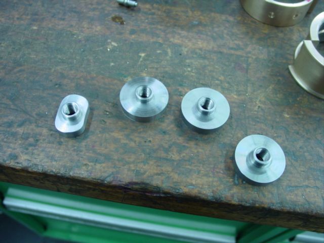
Here are some photos of some of the bits:

attachment.php


attachment.php


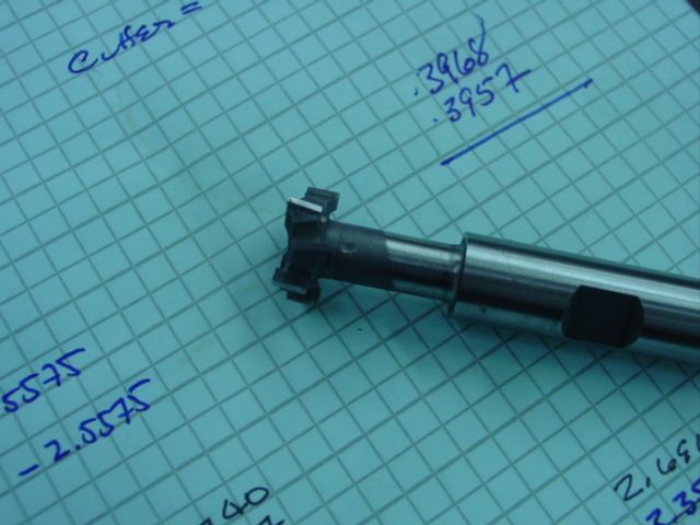
My first question concerns the long shaft shown here:

attachment.php


This has about 1mm = 0.040" of end-play. Is it meant to have this, or should the front bearing "capture it" in the axial direction? If the axial play is not meant to be there, then I think that to access that bearing, I need to remove the front bevel gear. But the bevel gear is completely free of play, so I'm afraid to mess with it. It has a triangular jack-screw plate beneath it that seems to be setting the location and/or end-play. If necessary, can I remove this bevel gear to get to the bearing for the long shaft, and get it back into the right position without special tools or techniques?

attachment.php


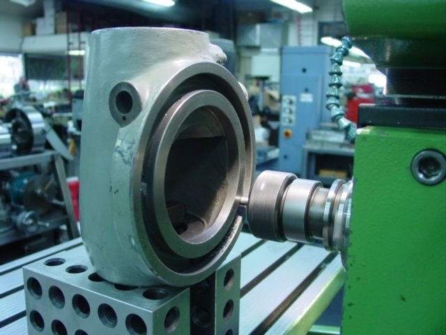
Second question, here is the rear bearing:

attachment.php


Is this rear bearing meant to be permanently greased, or should it be free of grease and instead get oil via the key slot of the long shaft?

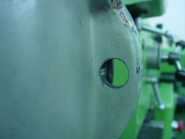
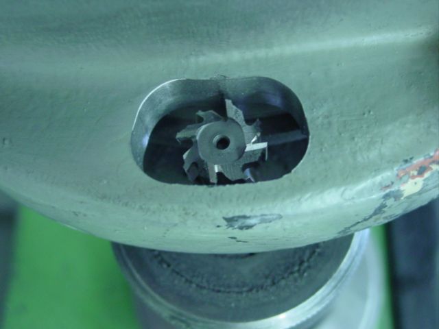
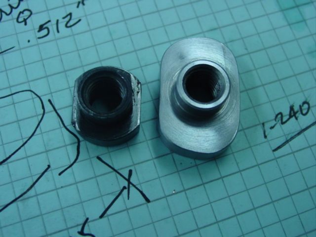
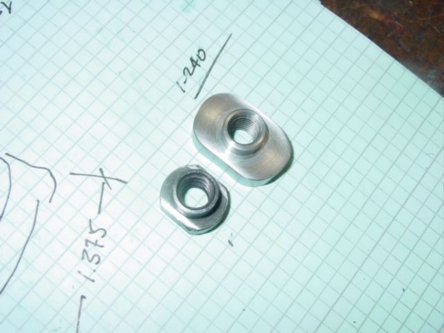
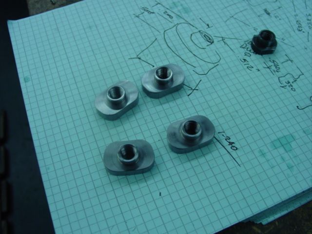
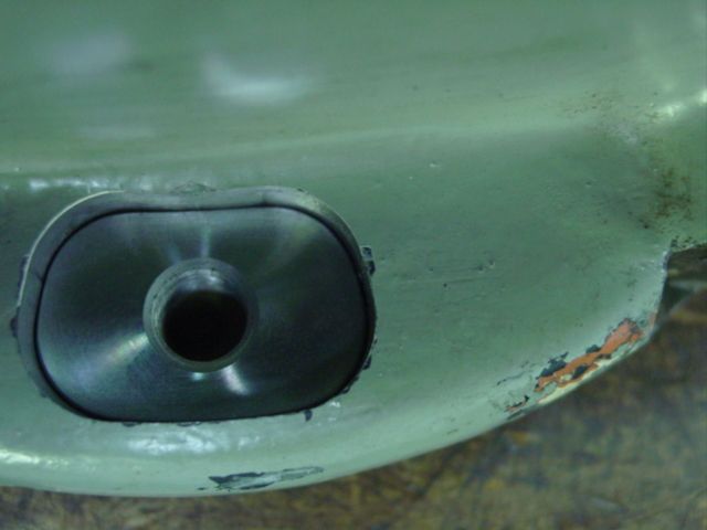
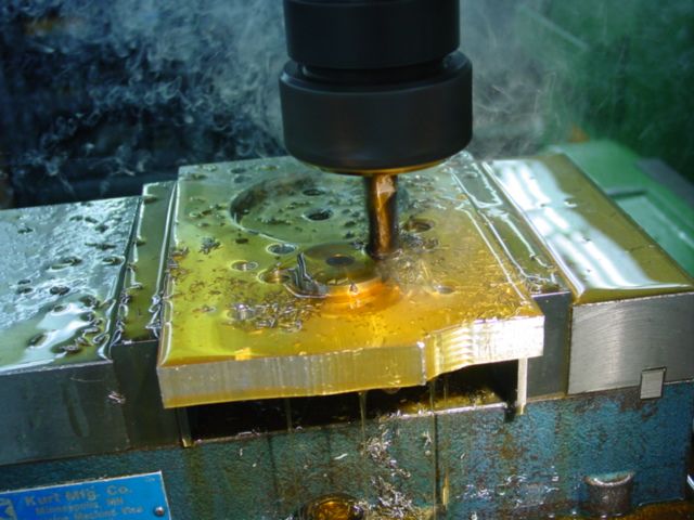
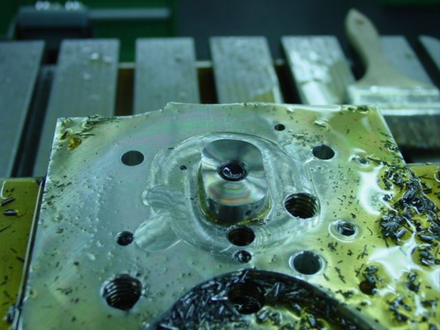
Third question: I'm not sure if I should clean up the rotary T-slot with a Wohlhaupter and single-point cutter, or if I should mount the casting on a rotary table with an angle plate and use a T-slot cutter. How have others done this? The slot opening is about 13mm wide, and the slot is about 17mm wide. Access hole from the rear is 20mm. So for example I could use a 16mm diameter cutter on an 8mm shaft.

Cheers,
Bruce
 
I think a T-slot cutter will be much more efficient than the Wohlhaupter if you can work out a practical setup to mount the casting on the rotab.

Make sure to use the largest shaft possible relatively to the slot width. 8mm diameter seems on the skinny side to me !
 
Bruce,
In regard to questioning the end play. I think that shaft is below the center line of the bevel gear driving the spindle and has straight roller bearings on both ends. There must be another pair of gears inside that are not visible but in any case a little end play sounds reasonable.
As far as being permanently greased or getting oil from the shaft, my vote is to have some grease in there. I don't think straight rollers require much though, only a light coating and definitely not packed full. I don't believe oil will ever make it into that or the front bearing the way that Deckel has it set up.
Remember; this opinion is only worth what it cost. I did have one of those heads for a while though and looked at it pretty closely.
Dan
 
Last edited:
Erik, I found Wilfried's photos some time ago, and I've already corresponded with him. He sent me a bunch of additional photos as well. I'll ask if I can post them here.

Tien, regarding the size of a possible T-slot cutter, the shoulder of the slot is currently about 2mm wide, that's part of the reason it is so easily damaged. I'd like to enlarge this to about 3.5 mm if there is enough meat there. If I have 0.5mm of clearance this means that the cutter diameter is 8mm PLUS shaft diameter. Since this has to be < 17mm to fit into the existing slot, I am restricted to an 8mm shaft.

Danny, yes, I'm talking about the long shaft below the level of the bevel gear at the front. Regarding lubrication, the grease in the back makes some sense. I'm pretty sure that the front bearing gets oil from the oil nipple on the top front of the head, so does not need to be greased. But I'm still not 100% sure about the rear bearing, because I can see that the two key slots in the long shaft are covered with oil, and that certainly runs down them and reaches the rear bearing.

Regarding end play, Indeed there is a needle roller bearing in the back, and I'm pretty sure from the drawings that it is the same in the front. But doesn't it need SOMETHING to control the end play, ie some bronze washer or bushing against a shoulder? You don't want to leave this end-play control to the needle cage butting up against the hardened washer or shoulder, right? So I'd like to have a look at that front bearing, but I think the only way to access it is behind the front bevel gear. (Danny, if you have any photos from behind that gear, please share!)

Has anyone here removed that bevel gear in the front? Is the triangular plate with the three jacking screw to adjust the end-play of the bevel gear bearing? Or is it to adjust the mesh of the bevel gear? If so, how hard is it to adjust, and how does one go about it?

Cheers,
Bruce
Hi Bruce,
The reason I say it won't get oil (or enough) is because on older FP1 heads they put an oil nipple on then to oil the rear bushing. That bushing is right next to the gear that slings oil into the gutters to suply oil to the Y axis slide ways. I reason that if that bushing won't get oiled properly then I'm sure thos bearings won't either.
No pictures of a disassembled long reach head but I have had the bevel gear out of one similar. That piece with the adjustment screws puts tension on the front bearing setting it in a preloaded condition. It is sprung and will have a gap between it and the casting because of the adjusters. When the bolts are drawn down to tighten it the gap it has behind it is pulled tighter. I don't have any idea what the factory procedure was for setting it, I chose to mark the location of the plate and reinstalled it the same as it was without disturbing the adjustment screws. I do remember those bearings were greased when I took it apart so I did pre-grease them before I reassembled it and have had no problems with it.
Hope that helps,
Dan

On Edit; You probably won't be satisfied until you take it all apart and look it over real good. The reason I don't think the end play in that shaft is anything to worry about is due to function. I think there is a straight cut gear on the end of it and it will simply find the sweet spot when under load. The roller bearings are not that particular as long as they don't get to either end of their race ways.
 
Hi Danny,

I've seen how much oil gets up to the gears that drive that shaft, and it's a LOT. Now those gears are enclosed and the enclosure runs back and forth along the shaft. That definitely leaves oil in the key slots. But hard to say if enough reaches the rear; probably grease is the safe option. I'll write to Franz Singer and ask him to be sure.

Regarding float of the long shaft, I'm torn. My dad passed away a few years ago, but I can hear him saying "if it ain't broke, don't fix it!". The point is, I'd be happy if that head got quieter, but don't know if it is as quiet as they come, or noisy, since this is the only one I have ever heard in action. Anyway, I'll wait another couple of days, but probably will mark the jack scew head locations then remove it carefully to keep the settings.

Related question, I think I am finally going to start doing some painting to make this thing look nicer. Can someone in Germany (or the Netherlands, Peter, that's close enough, and I am sure I can get the products here) recommend specific brands of filler, primer and paint that work well? I have heard that 2K PU paints are a good choice, but am not sure. I want to brush or roll, not spray. I have seen RAL 7005 (Mouse Grey) and RAL 7010 (Tarpaulin Grey) RAL 7016 (anthracite grey) RAL 7040 (window grey) and RAL 7045 (telegrau = far grey) all mentioned as matching colors. Any idea what would be best for a 1964 Deckel gray?

Cheers, Bruce

Cheers,
Bruce
 
Bruce:
Wrote about repairing the "T" slot of an FP2 Vertical head several years back... Posting is still up but not the photos....
Here is my approach...won't help you exactly as this was done on my FP4NC.....but perhaps some ideas

DSC01836_zps9btmzhac.jpg


Setup running horizontal ...used the end face of the housing as a reference....Through hold down ..Indicated mounting face..
Used "T"slot cutter to tune up the slot....Needed to neck the cutter some to get enough reach.

DSC01843_zpsxfky0rbr.jpg


Cutter inserted through original access hole in casting (normally plugged) ....

DSC01840_zpseodqqlim.jpg


Hole was reworked to a sort of kidney shape using the "T" slot cutter....

DSC01841_zpsh7rk06po.jpg


More to follow....
Cheers Ross
 
"T" slot was cut deeper on the mounting face side to clean up damage done by cavemen doing weight training using the clamp bolts.

Further the slot was also made a bit wider both inside and outside surfaces of the "T"......

New "T" nuts were made in a shape to follow the "T" slot shape (curved) to give more surface area....as compared to the originals...

DSC01855_zpstgqxrxdn.jpg


DSC01857_zps55mee9qz.jpg


New nuts were profiled from 4142 heat treated (RC 32) material

DSC01860_zpsybilyocc.jpg


DSC01854_zps1cczrmla.jpg


Shot of the modified T nut being installed..................


Cheers Ross
 
Ross, thanks for reposting these photos. I came across your thread about this some years ago, but indeed the photos had disappeared. Here is a question for you, how wide did you make the shoulders on the new T-nuts? The old ones are about 2mm, it looks like the new shoulders are somewhere in between 3mm and 4mm wide. That, plus the longer T-nuts, make a big increase in the clamping area. Also, what was the OD of the 4142 round stock that you used for the nuts? Cheers, Bruce
 
Bruce:
Material started at 1 3/8" OD.....

Width of the nut at the center is just over 20.1 MM....(.792") but that dimension changes because the part is curved.....Works out at about 3.5mm on each side.

Size was based more on where i got acceptable cleanup of the slot....On the head i repaired there was chipping of the edges where the bolts were over tightened.
did not get 100 % cleanup on the clamping face and that is why i went larger on the nuts....I personally think the factory nuts
are too small a contact area for the iron.....A little too tight and things go south in a hurry....especially when the nuts get clamped in the same spot most of the time...
Cheers Ross
 
Ross, thanks, I'll do something similar, will start with 35mm stock for the nuts. One last question, it looks like you took the same amount off the ID and the OD. When Wilfried did this, the ID of the slots was damaged, but not the OD, so his nuts have a "step". It looks like the OD of my slots is damaged, but not the ID, so I am thinking of only cutting down the OD, and thus having nuts where the two shoulders are in different planes. Do you see any reason not to do that? Cheers, Bruce
 
Not exactly sure how you are seeing this.... Personally i would not wish to make the heights of the nut different, Want the best chance of getting even pressure on both sides.

For me, using a "T" slot cutter it was not possible to make the faces different heights......Cutter makes them both the same....if i understand your question...
This is the reason i personally would not use the boring head to do this work....Difficult to get a truly flat surface on both sides of the slot.....

Cheers Ross
 
Setting up to do this with a T-slot cutter, unfortunately not CNC. I'm going to enlarge the shoulders from 2mm wide to 3.5 mm wide.

attachment.php


attachment.php


Because I would hate myself if the head shifted while I was working on it, I'm going to turn a 70mm stub and bolt/pin it to one of the angle plates. Then I can use the quill lock to tighten down on that, for some extra clamping. I'll post another picture or two as this proceeds.

Cheers,
Bruce

PS: I'm still trying to remove the two layers of green paint that someone sprayed over the factor grey paint. In some places the green paint flakes off. In other places it is very tenacious and hard to remove.

I want to play around with some chemical paint removers, to see if I can find one that will attack/bubble the green paint layers on top but will not attach the original grey stuff. Does anyone know what TYPE of paint was used in the 1960s by Deckel? I am thinking that this might have been picked to be quite resistant to basic (alkilii) substances, so perhaps a lye-based paint stripper would leave the deckel gray alone but blister the other stuff.

Cheers,
Brc
 
Hi Bruce.

Obviously, you don't have a Centricator to center the spindle to the round table and then the workpiece.....

Regarding control of the play in the long axle, I just had a look at the standard head - maybe it's made the same way?

I suppose you have that parts manual for an old FP2, as I gave scans to Alan to include it on the DVD.

FP2Hovede.jpg
 
Hi Erik,

Obviously, you don't have a Centricator to center the spindle to the round table and then the workpiece.....

Actually I DO have a cheap Chinese Centricator, but I don't think it's the best way to center the work on the table. This is more like centering something in a four-jaw vise with all four jaws independent of each other.

Regarding control of the play in the long axle, I just had a look at the standard head - maybe it's made the same way?

It's not, because on this standard head the long axle is also the mount point for the bevel gear that drives the spindle. On the long-reach head the long axle is not connected to the bevel gear.

I suppose you have that parts manual for an old FP2, as I gave scans to Alan to include it on the DVD.

Indeed I do, and I am very grateful for it!

Cheers,
Bruce
 
Looks good. Will be better than new!

Only can add something about fillers. I am using Akemi filler. Works good on my mill, repairing whole stripped sections or filling imperfections. Pretty strong, easy to sand, chemically resistant. I believe it is a German brand so should be easy to source for you.
 
Hi Botje,

I am using Akemi filler. Works good on my mill

Could you tell me exactly which Akemi filler? Indeed it is easy to find here, - a quick look online finds many different types. Akemi's main market seems to be for filling cracks/gaps in stone (marble, granite, and so on).

Are you sandblasting to prep the surface, or something else?

Cheers,
Bruce
 
Relative to the long reach head... (at least based on the drawings in the manual i have) that i believe some end to end movement is normal for the long drive shaft....
Looks like the shaft is carried by roller bearings at each end and looks to have a plain thrust/shim washer to control free play and limit position.
I would expect .004-.008" of free play using that setup...no reason to run any closer.

Bruce , good call on the setup.....More work doing this setup but I think you will be happier going with the "T" slot cutter!

Erik:
Centricator aligns a bore or hole relative to the spindle rotation....Not exactly what is needed here as Bruce really needs to get the part centered with the center of rotation on the rotary table. Position of the spindle is
relatively unimportant for the initial setup.
Further he must also get the part flat with that same rotation...Something a Centricator would not give....Think his setup is exactly what is needed.
Cheers Ross


Back
Top