What's new
What's new

New dialog 2 project

rimcanyon

Diamond
Joined
Sep 28, 2002
Location
Salinas, CA USA
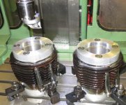
My first dialog 2 project on the fp2NC was motivated by a project to restore a 1967 BMW R60 motorcycle. I need to bore a pair of cylinders to the next oversize. I wrote 3 dialog programs, and along the way got the fp2NC working reliably along with the help of Herr Singer.

Here are some photos of the project. The first program created the vise jaws on the right, the second created the top torque plate, the third created the bottom. The third program rotated the axes 90 deg. 4 times.

More to come, since the cylinders aren't bored yet. I'm waiting for some 10x55mm cap screws. I also need to mill the bottom torque plate perpendicular to the vertical head, and add some keys on the sides so that I can get the vertical head reasonably aligned with the cylinder. Right now the table sags in front about .001" in 5", so the fp2NC really needs to have the Z axis gibs reground. That will happen after the cylinders are bored.

If I could figure out a way to post the programs as an attachment I would.

IMG_2192.jpgIMG_2193.jpgIMG_2195.jpgIMG_2196.jpg
 
Last edited:
Dave:
Nice to see you making use of that machine ....Give it a serious run and i guarantee that you
won't be going back to your manual FP2 for anything that will run in the envelope of the FP2NC.....

Wondering just what did you get from Singer that solved your running issues?
Cheers Ross
 
Ross, the biggest headache I had was with coolant. I had leaks everywhere (from hose fittings, drips from the enclosure, internal drips that filled the sump at the rear, and one large leak from the right rear of the machine that was hard to pinpoint). Some were easy to solve, but the one at the right rear left a big puddle after using the machine for a few hours. It didn't seem to have a drip, it was just a slow leak that was due to two things: the hose had a kink so coolant running to the drain at right rear backed up above the drain, and the metal drain fitting was leaking, either internally or around the outside. I think it was an internal leak, since there is a bunch of silicon sealant that was added by someone.
IMG_2198.jpgIMG_2199.jpgIMG_2200.jpgIMG_2203.jpgIMG_2204.jpg

Singer provide a replacement drain hose that won't kink and includes a new grey plastic drain fitting that is bonded to the hose. I installed it with lots of Loctite 567 to fill the voids. I'm not sure it was the best sealant to use but it works and I had it on hand. The original sealant was much thicker, and I think the 567 is too liquid. However, it did not leak when I used the machine yesterday.

I think the reason I had enclosure leaks is that I was using a Kurt vise to hold the parts I was making, and the coolant flowed out the rear of the vise close to the column. I also installed new way wipes from Singer, but the old ones were in very good condition, so I don't think that is a factor. I think when I use the vise again I am going to mount it with the jaws parallel to Y axis, so coolant will drain into a table slot.

I really enjoy the Dialog programming and the quality of the parts that result. But I'm not there yet. With a manual mill I seldom make mistakes, and I can run iterative tasks with intuition, just focussing on the one critical dimension, but otherwise operating in the zone, or thinking about the next step. So far I don't have that kind of intuition for Dialog. The biggest lesson I have learned is to keep my intensity up and focus on each step.

-Dave
 
Dave,
Nice looking job on the torque plates. This interests me because I want to bore some cylinders on an FP1, I think a little larger than what you have (3 5/8" Diameter X about 7" length. My plan is to make a 1 1/2" adapter to put the boring head on, long enough to clear the bottom or the bore. I don't know if the machine will be rigid enough to do an adequate job or not. I have looked at some of the kwik way and van norman set ups for automotive work and they seem pretty flimsy but have been in use for decades. Are you planning to use the Z axis travel to bore the cylinders? I for one would like to here how they turn out.
Dan
 
Danny/Dave:

Have done lots of boring on my FP4NC over the years...Some thoughts on this. First off is possible, run your boring work using the horizontal spindle....
Because of the construction it is my belief that the horizontal spindle is more rigid has better support and gives smoother operation by eliminating the gear "noise"
of the bevel set.....

If i was going to do long bores in specific on an FP1 ..Would think about making a "Boring" bar setup.....In short i would use some thick walled tube machined to fit around the extended quill of the spindle being used....
The tube would have a long plain bushing at the far end ( lube long enough for the reach needed)
A stout shaft would fit into the spindle taper and continue through the bushing and enough beyond to make up with your boring head.....Advantage here like a purpose built cylinder boring machine (Kwik Way, Rottler etc)
is that you get support close to the point of the cut...keeps the tool running true and dampens vibration (the killer on long overhung work).

Its a bit of work...but might be worth the effort depending on the job .

In my own situation i almost always use the horizontal for long overhung work.boring included...(FP4NC) I have the luxury of owing a selection of Sandvik "Capto" boring tooling..and for me
that makes all the difference....4" bores 8-10 inches from the spindle nose in cast iron are not a problem....Can hold .0003" on the diameter no problem.
Cheers Ross
Ross,
I agree that the H spindle would be a better option but due to limited travel on the FP1 it's not going to happen.
Boring my own cylinders has been on the back burner for a while and I have a host of performance parts for that engine but require .005" OS for the pistons I want to use, OS pistons only in that compression ratio. Some shops would probably do that whole job on a Sunnen hone but my shop doesn't have one, there in lies the desire to try this out on the FP1.
The out board support idea is something I may look into and totally doable, also a hollow extension for the boring head may be just the ticket without extra support. The speed and feed may be a non issue vibration wise if everything is just right, steady chip load and small depth of cut with the smallest radius etc.. All good points and I will report on this in the future although Dave will probably have it all here first (a test pilot).
Dan
 
DI have the luxury of owing a selection of Sandvik "Capto" boring tooling..and for me
that makes all the difference....4" bores 8-10 inches from the spindle nose in cast iron are not a problem....Can hold .0003" on the diameter no problem.
Cheers Ross

Ross, similar to this? This one goes from 49.5 to 71.5mm, which is too small. It's a bit beyond my budget too, at $750.

View attachment 141101
capto_boring_head.jpg
I need a boring head that is about 7" from the 40 taper flange to the cutting edge. My collection of boring tools is pretty basic, the best I can come up with is this:

IMG_2210.jpg

Both will bore to 75mm, although that is about the limit. The bottom one is more rigid, and the cutter is right at the end, so it is the one I am planning on using.

Also, you mentioned one advantage of horizontal is less gear noise. I assume that advantage is only a factor if the bore is not going to be finish-honed. So for engine cylinder boring, would the vertical head do an adequate job?

-Dave
 
Dave:
Yep that is like one of the heads that i have.....Cost is higher than you think as that head requires a base piece to fit your spindle...along with a coupling piece .....and on+++!

Stuff is very nice, couplings are rigid and repeat for alignment and all...Very tight tolerance stuff..the three sided "polygon" has a slight taper and it nests into a mating male
socket that when drawn up not only the taper get tight but the square shoulder at the end of the polygon also butts up tight. Sort of the tool holder equal to a "Big Plus" spindle...

Don't think the reduced mechanical "noise" will be a factor in your job...Your setup looks to be workable....If using the tool with the insert tooling, try to find an insert with positive
geometry...Will not be shock resistant and will wear faster, but positive tools will reduce the forces acting on the head....

When i do a long large bore like that on the CNC...When the tool gets to the bottom of the bore. i program a shift to neutral (S+0) and call a program stop (00)...before retracting

I rotate the spindle by hand to orient the cutting edge (sharpie mark on the shank) either toward the X, or Y axis (if running vertical)
Then i program a small move to the tool along the oriented axis in the proper direction before extracting the tool to the Z tool change point....What i am doing here is having the machine
move slightly so the tool won't drag when it moves up to home....
Further once at home having the spindle in neutral allows you to quickly rotate the boring head so you can easily see the setting dial for the next cut....

Just remember to orient the tool or you could get a nice groove if the tool happens to be pointed toward teh axis move instead of away...

Cheers Ross
 
I used the surfacing program to re-face a Porsche flywheel yesterday. It took a lot of iterations of different cutters and tooling to find something that worked to my satisfaction. The clutch surface is actually recessed inside, so the cutter used needs an overhang. The steel in the flywheel is also quite hard and tough, probably chrome moly 4140 or similar, and the cut is interrupted. My selection of facing cutters is good, except finding something that could deal with the overhang. So I ended up using the cutter shown in the vertical head, some of the others I tried are next to it. It is about ¼" too small so I ended up having to take two passes, and the overhang was more than the clearance the tool afforded, but I think its ok.

The tools with too much cutter surface contact didn't work well at all. The flycutter worked except that the surface that resulted was not flat, it tapered up from the edge to the recess.

IMG_2216.jpg

There are still some spots of wear showing so another pass is needed. Next step is to finish the top surface, where the pressure plate sits. I ran into one of the limitations of the FP2NC - the Y travel is only 9", so I can't use the cutter that is in the spindle. I either need to find a way to mount the flywheel vertically and use the horizontal spindle (X and Z travels are much bigger than Y: 12" & 16"), or use a large dia. facing mill turning in a 9" circle.
 
I found another std. cylinder to match the one I already had, and bored both to first oversize. Those are the cylinders I plan on using for this BMW R60/2 engine. The cnc program had to be modified a bit, but it still resembles Ross' suggested work flow. Now it bores one cylinder, stops at the bottom so the cutter can be aligned for exit, then when restarted, it backs away from the cylinder wall, exits the cylinder and bores the second cylinder, stops for the cutter to be aligned, then repositions the boring head for the next pass over the first cylinder, stops to allow adjustment, and repeats. It would be just as easy to do four cylinders at once, etc., which is the beauty of a Dialog machine. The changes to the program to do 2 cylinders amounted to 3 blocks: change of coordinates, repeat the blocks to bore the cylinder, change coordinates back.

I need to bore 4 cast iron cylinders for a Porsche 356 to fit some new forged AA pistons, so I will be revisiting this again.

The results came out better than I expected. The last pass was repeated twice, which seems to improve concentricity. The bore is concentric within .0001". The other thing I found that improves concentricity is to remove less at each pass. The first time I did this I was removing .005"+ at a pass. I got better results with .003". It will be interesting to see how they turn out after honing.

Here's a photo of the setup, after the final bore:


Attachments

  • IMG_2296.jpg
    IMG_2296.jpg
    91.8 KB · Views: 138


Back
Top