What's new
What's new

Porsche 911 Engine Machine Work

Nice...
Have done a bit of that sort as well....Worst part is re-boring the jack shaft bearing housings after the case halfs have been clipped.
Can hardly see the inner bore, let alone measure and hold size. There are factory reamers for this sort of work, but they will chase the original bore,
me i want to be sure everything is actually straight

Need long reach with not too much OD on the bar....The one pictured is shop built.

DSC00359_zps97a68d98.jpg


Thanks for sharing...Love to see how others attack and setup off sized jobs....Universal table is a real help here getting everything in tram....

Cheers Ross
 
Setting up one of the case halves to do what is known on the west coast as shuffle pinning.I just call it dowel pinning.In order to keep the case from shifting.


deckel 115.jpgdeckel 116.jpg

I place my pins on the outer edge of the main webs. The above photos are before pin bore machining.


deckel 118.jpgI made a drilling reaming cycle to do this.If I do many more of these I am going to make the mirror image jig I planned up.
 

Attachments

  • deckel 112.jpg
    deckel 112.jpg
    90.1 KB · Views: 1,371
Cool Ross,So I'm not the only crazy sob that would attempt this :D.I like to see others set ups as well.I got my bar from a real good dude on ebay.Was browsing his large assortment of used boring stuff, messaged him what I was looking to do,he sent me mine for 50 bucks shipped.I still had to modify it and hone the carbide:).

What is your method for lining up the main line with the Y axis? I'll be getting to my method in a bit with a few photos.

Do you line bore your mains with your bc4 or do you use a factory or other bar?

Regards,Mike
 
While I was there I did an oil pisser modification.deckel 135.jpgdeckel 122.jpgdeckel 133.jpg


deckel 137.jpg
Sometimes you find in the middle of a job you have to make something to complete that job.
 
What is your method for lining up the main line with the Y axis? I'll be getting to my method in a bit with a few photos.

Do you line bore your mains with your bc4 or do you use a factory or other bar?

Cool work

I had to do some more modest work on VW flat four crankcases as well.

My method for lining up the main line with the spindle axis was to tram the case with the gearbox/clutch plane for reference first (gives the "direction" of the main line), and then indicate one of the bores (gives the "location").

To be real sure, I used to "map" the errors in the gearbox/clutch plane first, using an indicator attached to a bar spun in the crankcase (with added journals at both ends).
The case was then trammed taking the errors in account.

I have pics I can post if you wish so.
 
Do you guys scape the parting plane flat? I have never seen that before (but it makes absolutely sense).
This was a rhetorical question, I see the blue and the marks. There is no doubt.

I did make have some 911-machining too: :)

911-1-1.jpg911-1-2.jpg911-1-3.jpg911-1-4.jpg

Could make actual machining pictures next week. But there is nothing exciting about it. All between and including the webs is milled (on a MAHO). But lathe work is on a Haas.

Nick
 
Mike:
Do the 911 mains on the BC4. Too long i think to get a good job on the Deckel.
With the 4 cam cases i do the mains and jack shaft totally on the FP4NC...
Tram by indicating (sweeping) the main bore at each end of the case with checks of the intermediates to double.
To allow for bar sag i indicate both ends of the case from the far end of the bar that will do the cutting at the length it will be used.

I have a "Capto" fine boring setup with extensions that does a good job off the horizontal spindle for the mains. The long reach Capto vibration damped small bar
that can do the jack shaft is way too pricey for my blood...last i checked it was almost 4K for just the bar
For me i find that the fixturing of the case when boring it is very important...easy to distort the 4 cam cases...

On your shuffel pinning...do yo bore both case halfs to the l same dowel size or do you give one side the "press"?

Don't know anything about the oil mods.( i am not really a Porsche guy)..with more "outlets" do you have to do something to increase the pump capacity?

T:
Yes by all means i would love to see your work on the flat 4 case....

Nick:
Nice work...did you have a drawing or a real part to scale or did you do all that from photos?
Is there more of the engine done or to be done? Photos?

Cheers Ross
 
Ross,I priced kaiser etc. for the bar.It just came down to the $ for tooling was going to kill the profit at the time I did the first one.If I knew for absolute certainty I would use a bar that size more I would buy a new fancy one, Some time I will go as far as breaking even on tooling because I will have the tools in the end but going negative just was not appealing at the time.Funny thing though I did just need a bar to do a odd repair for an older heavy forklift hyd. valve body bore ,multiple lands and grooves (I think about ten) in an iron block about 8" end to end. I believe the bore needed to be about .945(the chrome shop would finish piston to size). Ended up making a plate to bolt a vise to the cross slide of my clausing and used an adjustable king pin reamer with a rather long pilot end to "line ream" it (I think I just made that term up:))


"On your shuffel pinning...do you bore both case halfs to the l same dowel size or do you give one side the "press"?"

Yes I make one side about .0005 tighter, these things are a real mother to split.One could fit them looser but that would defeat the purpose especially with the aluminum/magnesium growth.

"Don't know anything about the oil mods.( i am not really a Porsche guy)..with more "outlets" do you have to do something to increase the pump capacity?"

Most of the oil mods are straight forward although at somewhat awkward to get to places.And most of them were developed by the factory and incorporated in later engines, but not this early 2.0 aluminum case.With the oil bypass mod you typically use a late style pump and have to use the late bypass pistons.The piston squirters are very small orifices and are ball valved so little loss there.

TNB,The more pictures the better!

Nick, I like the mini crank, would make an interesting desk or mantel display.deckel 202.jpgOil hole mods. to a full scale one.
 
Most of the following photos are of a bit lower quality.One of my little monsters decided to take 300 plus pictures of the ground and change the settings on me.Took me a while to work the bugs out of the camera on that one:D.


deckel 174.jpgdeckel 180.jpgdeckel 178.jpgdeckel 179.jpgdeckel 181.jpg

Autocollimated the case in to align the mains with the true spindle axis.Question is how close did the germans get it with the Y axis.I didn't piss around to find out,probably don't want to know anyhow or else it will be one more thing I will have to remember to compensate for:D.

The last sentence might sound a bit ignorant to someone unfamiliar but I can actually see the error in the spindle rotation with this method. There is no car factory in the world that would approach this accuracy(not going to take the time in a production setting).So not saying F-it it's good enough.:D
 
Last edited:
deckel 185.jpgdeckel 186.jpg
I don't need no Fan$$y corporate bar.:D I've got my proprietary anti chatter wrap, got tooled up at my local schwinn shop on this one.


deckel 191.jpg
Balls deep:eek:.
 
I don't quite understand...How do you get the autocollimator true with the mains in a case that has been scraped , where the bores are no longer round?
Can you show the tooling to locate the scope in the housings.
How do you account for the droop of the bar?
When running the BC4 i compensate for droop between the main supports by raising the bar with a center steady based on the span and the bar diameter.

Cheers Ross
 
Ross,
Bored the int. shaft hole after line honing the mains.The tooling is just two cyl. ground rings.I did not bore the mains in the deckel if that's what your referring to.The droop would be irrelevant if you are using the same cutting point to bore all the holes I would think with a standard bar supported only at the drive end as the droop would be the same for all the holes aside from the axis itself sagging.

Have you ever had any of the front main bearings in your hand of these engines?If so did you happen to mike them?


Regards,Mike
 
Mike:
Did not figure on the mains being honed...Just did not think about it. On that Porsche the main centerline is not too critical.
Here, we deal with so many gear driven overhead cam setups that honing the mains is not an option..never know where the finished centerline ends up.

Re bar droop....was commenting relative to the scope setup....Yes the droop is the same but the actual bore will of course be lower than the
scope indicates....but i just did not realize that the "boring' was only being done on the counter shaft, and you were using the scope only to get the axis aligned.

As to the front mains..have had factory units in hand, never made any.
Did you do your own setup ground rings for the scope?

Cheers Ross
 
Since you asked, here are a few pics.
A friend of mine asks me to bore the mains of VW crankcases from time to time.

Of course, this is a rather easy job that numerous specialized shops perform everyday for cheap, but at first I thought why not give it a try, just to see how it feels in Ross's shoes once in my life ;-)

So I tryied to figure out a way to do it. My first idea was a corddrill driven boring bar of my fabrication, with the bar spinning in two added bronze bushings. Nothing new here, there are a lot of examples on the net. So I made a bar and two add-on journals from bits lying here and there. The bar was driven by the mean of a ball end allen key, minimizing operator's input.


Then I realized I'd have to face the walls next to the bore at the clutch end too. Since I couldn't figure out a reliable way to control the depth of cut of the facing tool with my set up, I decided it would be more efficient to do all the machining in one setup on the Deckel. Considering the versatility of the machine, I would necessarily find a way to do it.

To get gravity and boring bar drop out of the equation, I decided the vertical route was the way to go.

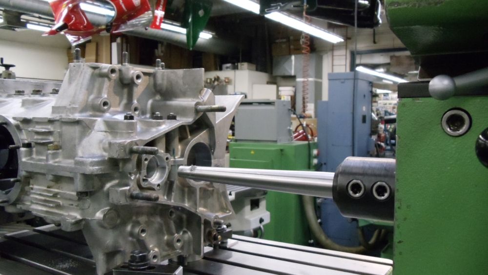
So here's how it goes : the crankcase casting is clamped directly on the longitudinal carriage of the FP1 via an old shaper T-slots cube. That setup allows me to tram it both in x and y axis.

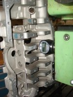
As I told you before, I first map the errors of the clutch/gearbox plane, using an indicator attached on the boring bar spinning in the added journals.


From my limited experience, those assembly planes are often far from beeing flat.
When I have the numbers, I know how to tram the cranckcase relatively to the spindle axis.


Then, I center the spindle, indicating the lowest bore of the cranckcase.
I do it that way because I will use that bore to support the end of the boring bar, with a pressed in journal (a ring with the OD turned to the exact diameter of the bore, and a bronze bushing for the bar).
So the upper end of the boring bar is held in a collet in the spindle (spindle, collet and bar marked for the lower runout position), and the lower end spins in the added journal.

I feel like this is the way of doing things that will allow me to get the best "average" reference, between the original line of the mains, and the plane of the gearbox/clutch (wich seems almost as, if not more important to me).

As I said before, I've adopted this method since it was the easyest. I've never have good luck trying to align two bores at a time... My attempts to get centered on the second one always result in getting off the first one and I always end up chasing my tail for hours.
By tramming a plane first and then centering a bore (direction/location), things get a lot easyer.
The rest is easy.

Note that the pic below was taken during the mounting of the boring bar. The machining operation starts with boring bar almost fully engaged in the crankcase. The travel used on z is no more than 30mm, each bore beeing machined by a dedicated presetted tool.


At the end of the operation, I even face the gearbox/clutch plane, in order to get everything as straight, square and true as possible.


Anyway. As the process was a bit tedious nevertheless, I figured out an easyer way yet to do things a while ago ;-)

As the reason for using a milling machine was the need to control the feed of the boring bar, I tought I could have the best of both worlds using a cordless drill to drive the boring bar spinning in bronze bushings attached to the crankcase, AND the Deckel feed.
All I had to do was to clamp the crankcase on the table of the machine so that the end of the boring bar would rest against a ball bearing attached at the end of a shell mill holder (in the spindle, that is).
The boring bar beeing supported by added on journals, no need to tram nor center the crankcase.
It's easy then, to push the boring bar with the cord drill with one hand, while turning the x-handwhell with the other to gently control the feed. One can even use the auto feed and the stops of the machine !


Back
Top