What's new
What's new

Rebuilding an old Deckel FP1

jbentley11

Plastic
Joined
Aug 19, 2016
I am in the process of rebuilding the old Deckel FP1 shown in the following photos and it has been suggested that a write up may be of interest to others.

Test.jpg

Test2.jpg

The main body casting is stamped with the interlaced FD symbol and FP1-44-23843 as per the following photo, so I assume that the 44 relates to 1944 as the manufacturing date of the original machine.
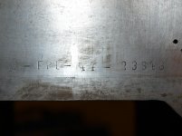
PA169870.jpg

The machine has been rebuilt previously by Precision Grinding Limited here in the UK (Mitcham, Surrey) and sold badged as an Alexander machine. As part of this rebuild the machine was fitted with a roller bearing horizontal spindle and an Alexander vertical head and slotting attachment. Although Alexander Master Toolmaker machines were near copies of the first generation Deckel FP1 they differed, as has been noted before on this site, in being fitted with 20° pressure angle gearing rather than the 14.5° used by Deckel. However, in the case of my machine the vertical and slotting heads are fitted with 14.5° gears to mesh with the original Deckel gearing.

Although purchased over two years ago the machine has been stored in the garage until I commenced the rebuild in September last year, although some preparatory work was undertaken earlier. I do not propose to describe the detail of the work, but to provide an overview of processes and sequence I am using.

As was intending to scrape all of the slides; the first activity was to manufacture a bevelled straight edge shown in the following photos.
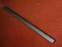
P1290234.jpg

The straight edge is 34” long to allow it to be utilised for the main ways on the vertical face of the column. I established the angle for the existing dovetail slides by using a vernier protractor at the extreme top of the front column where the slide is completely unworn. The angle of the table and saddle dovetails where also checked on the least worn sections and were found to match the 60° of those on the column.

The straight edge was manufactured from a piece of continuously cast iron bar which was rough milled to shape and allowed to ‘weather’ for approximately 8 months before any further work was undertaken. It was then rough scraped before being allowed a further 6 months to ‘weather’ before finish scraping.

The scraping was undertaken using an old Biax and an inspection grade 24” x 18” granite surface plate as the master. The angle was checked with a vernier protractor.

I do not proposed to describe the stripping down of the machine, but in the next posting I will show the condition of the vertical slides and commence a summary of the processes I utilised for scrapping these surfaces.
 

Attachments

  • P1147193.jpg
    P1147193.jpg
    85.8 KB · Views: 893
Last edited:
John, I think the problem might be that your photo albums are not "visible" to others. Make sure you select the options which permit them to be visible to all. Cheers, Bruce
 
John, this is a good thing that you you propose, take lots of pictures. By the way, my FP1 has a broken gear, courtesy of the previous owner. I am curious how easy is it to dismantle the gearbox and get in to replace a gear. Right now I'm not even sure which one it is. You comments would be appreciated.
I don't fancy having my machine down for long so I have basically worked around it for now.

Thank you in advance,

Dan
 
Hi.

Since you have one of the changewheel models, you could extend the one or few sets of changewheels using a separate small motor on a VFD.
A friend of mine did that, and it was quite neat. Like one of the newest, square FP1's.

BTW, I have scanned a manual and made the pages into a PDF. It's off a 1938 FP1 and it has many good pictures and setups.
Send me your email and I'll send you a link to get it.

Cheers
Erik
 
Bruce,

Hopefully everyone can now see some photos. You were correct about the folder being set as private, but correcting this did not solve the problem. I also tried deleting and re-established the links, and even a new folder and linking to that but still no luck.

In the end I have deleted the links and inserted the photos direct from my laptop.

Cheers, John
 
Dan,

Thanks for you reply:

"By the way, my FP1 has a broken gear, courtesy of the previous owner. I am curious how easy is it to dismantle the gearbox and get in to replace a gear. Right now I'm not even sure which one it is. You comments would be appreciated.
I don't fancy having my machine down for long so I have basically worked around it for now."

I did not take many photos when striping down the gearbox because the process was much too messy to keep reaching for the camera. I think I concluded that you have to start by removing top shaft (with the long gear that the horizontal head engages with) first and then remove the two lower shafts. All of these gearbox shafts are stored in a box waiting cleaning at the moment. Does your mill have the same lever controlled gearbox as my machine?

Erik,

I was already planning to install an electric feed motor and have already worked out most of the details. I will describe this as work progresses.

Thanks,

John
 
You were correct about the folder being set as private, but correcting this did not solve the problem. I also tried deleting and re-established the links, and even a new folder and linking to that but still no luck.

John, I just checked and I can see both of your albums and view the photos from them (the test album and the FP1 album). That's a good sign. Could you cut-and-paste one of the BB (Bulletin Board) codes into a message, from one of those photos, so I can see what it looks like? The album approach *should* work and it's a better way to do these because you get larger higher-resolution pictures in your posts.

Cheers,
Bruce
 
The straight edge was manufactured from a piece of continuously cast iron bar which was rough milled to shape and allowed to ‘weather’ for approximately 8 months before any further work was undertaken. It was then rough scraped before being allowed a further 6 months to ‘weather’ before finish scraping.

The scraping was undertaken using an old Biax and an inspection grade 24” x 18” granite surface plate as the master. The angle was checked with a vernier protractor.

I do not proposed to describe the stripping down of the machine, but in the next posting I will show the condition of the vertical slides and commence a summary of the processes I utilised for scrapping these surfaces.

I am thinking that SE might be ok as long it lays flat on a granite or you have at least part of it on a solid surface, but i think it is too long to be not bendy. Put it up on a couple 123 blocks at the airy points and see how much it deflects. You either want to find a camelback SE or a granite SE.

dee
;-D

Dee,

Thanks for your reply. Having checked I notice that I have made an error in the length that I quoted in my original post - the length is 28” (the length of slide is 26”) and not 34”. I spent some time looking for a suitable camelback but without luck. It should also be noted that a camelback by its self would not allow marking of the full width of the surface of the slides because of the overhang of the dovetail.

The bible – Edward Connelly’s book ‘Machine Tool Reconditioning and the Applications of Hand Scraping’ point to the use of shop made Angled Straight Edges being used for such applications and notes that common lengths are 3’ to 4’ width of 2” to 4”.

Having made the choice manufacture a bespoke straight edge I undertook some rough calculations as part of its design. I am not sure why you refer to airy points as these are appropriate for length standards (supported at its airy points the two faces of a length standard remain parallel). I calculated the maximum deflection by assuming it a simply supported beam with a UDL. I considered the hogging associated with the 1” overhang at either end would be negligible. I calculated for the straight edge in both its horizontal and vertical planes. I cannot lay my hands on the calculations now, but as expected there is a significant difference between the maximum horizontal and vertical deflections. I could have made the section deeper, in order to minimise the difference, but choose instead to alternately spot the surface with the straight edge in the vertical plane along with other frequent checks from a datum surface that I will describe in a later post.

For the record I have just checked the deflection with the straight edge supported at 26” centres using a 2” diameter dial indicator reading 0.003” - 0 - 0.003”. The maximum deflect with the straight edge vertical is 0.0001” which I would consider acceptable for this application.

Cheer, John
 
John, I just checked and I can see both of your albums and view the photos from them (the test album and the FP1 album). That's a good sign. Could you cut-and-paste one of the BB (Bulletin Board) codes into a message, from one of those photos, so I can see what it looks like? The album approach *should* work and it's a better way to do these because you get larger higher-resolution pictures in your posts.

Cheers,
Bruce

Hi Bruce,

This should be followed be a photo two photos, one from each folder using BB codes.

attachment.php


attachment.php


Cheers, John
 
Hi.

Since you have one of the changewheel models, you could extend the one or few sets of changewheels using a separate small motor on a VFD.
A friend of mine did that, and it was quite neat. Like one of the newest, square FP1's.

BTW, I have scanned a manual and made the pages into a PDF. It's off a 1938 FP1 and it has many good pictures and setups.
Send me your email and I'll send you a link to get it.

Cheers
Erik

Eric, I have tried to send you a private message, but received a massage saying that you have "exceeded their stored private messages quota and cannot accept further messages until they clear some space"

Cheers, John
 
Hopefully the photos will show first time with this post!

The following photos show the condition of the front of the column before any work was undertaken.

attachment.php


As can be seen there were a series of scores and a significant band of corrosion. Scraping marks were present at the top of the slides and to a lesser extent at the bottom. The extreme top of the slide looked unworn as did a small section at the bottom left hand (looking from the front of the machine) adjacent to the dovetail. This latter location is unworn because of the taper gib strip.

attachment.php


attachment.php


attachment.php


attachment.php
 
The front face of the column was ground finish and I believe that the bearing surfaces were also ground. This is consistent with late Alexander practice and it is likely that the column was ground as part of the Alexander rebuild.

In initial assessment of wear was undertaken by measuring the depth of the slideways from the central section with a digital depth micrometer. This showed that the unworn section beneath the gib strip at the bottom was consistent with the top of the slides. The maximum wear in the centre of the slides was approx 0.001".

The following photos show further details of the initial condition of the column.

attachment.php


attachment.php


The final photo shows the unworn section adjacent the the dovetail underneath the gib strip.

attachment.php
 
John, thanks for the FP1 manual downloads; I noticed the machine serial number hand-written on the cover of "FP1 Parts" is #35118. My FP1 is serial number #35114, only four units away. Arno Martens indicated this machine was originally bought by Preci Tools in Montreal in November 1957. So it is the lever style gearbox, MT4 tapers. And to get around my transmission gear problem the machine has a 1HP DC motor with a variable speed drive, a good match for the FP1.
 
Last edited:
Apologies for the delay in starting the description of scraping the front face of the column, work; children and decorating have been getting in the way!

The starting point to select an appropriate datum. Edward Connelly’s book ‘Machine Tool Reconditioning and the Applications of Hand Scraping’ does not provide a step-by-step example of rebuilding a Deckel style of tool room mill, however, the best description of the method for scraping the column is in the Chapter on horizontal milling machines. In this Connelly utilises the horizontal spindle as the datum and scrapes the front face of the column utilising a “swing round test”. The stated tolerance is ±0.002” in 36”.

As noted in a previous post, the front face of my column is ground and as it is not a bearing surface could have provided a satisfactory datum surface. However, as shown in a previous post there were a number of scores and an area of corrosion, so I took the decision to scrape this face following Connelly’s notes. Now for the first problem, the horizontal spindle is not mounted on the main column and was to utilise the horizontal spindle I would have to allow for misalignment of the spindle relative to the column because of the wear to head slideways.

Looking at the shafts that are located in the column the gearbox input shaft looked the like the most suitable. I had already decided to replace both of the parallel roller bearings that support this shaft as the rear bearing adjacent to the drive pulley had significant wear. As I had yet to source replacement bearings and also I did not want to contaminate new bearings with cast iron fillings (or should that be scrapings!), I decided to turn a dummy shaft to fit directly into the column in the seats for the roller bearings. The shaft, which is shown below was turned between centres.

attachment.php

attachment.php


The shaft includes a shoulder to rest against the face of the column. The bar holding the indicator was made from a length of ¾” square bar. The indicator is graduated in to 0.0001”.

The edge of the bore in the face of the column was carefully deburred prior to inserting the shaft. The shaft was inserted without the length of square bar attached and the indicator mount on a magnetic base was used to check the shaft for any camming action. Unfortunately I did not take any photos of this setup, but the magnetic base was clamped to the face of the column with the stylus of the indicator bearing on the end of the shaft and the shaft was slowly rotated. No movement was detected on the indicator, confirming that the face of the shoulder of the shaft was true to the journals.

The following photos show the method of testing utilising a 24” straight edge.

attachment.php

attachment.php

attachment.php

attachment.php


I found that the bore of the gearbox input shaft was exactly vertical in across the face of the column but was close to 0.002” over the 24” vertical direction. This is clearly outside the tolerances specified by Connelly of 0.002” in 36” and is either an error in the original manufacture or an error when the machine was rebuilt by Alexander. To put it into context the error over the length of the gearbox shaft is 0.0005”

As the unworn sections of the slides were parallel to the top face of the column within 0.0001” I decided to scrape the face of the column parallel to the ground surface rather than to correct the inclination face and ways of the column to match the gearbox shaft. The dummy shaft, DTI and straight edge were used regularly during the scraping operations to ensure that I achieved this objective.
 
The first stage in scarping the front face of the column was to rough out front face of the column back to sound metal below the scores and area of corrosion. Frequent checks were made using a depth micrometer at each corner down to the unworn areas of the slideway to check that I was ‘scraping straight down’ parallel to the original surface. Checks were also made using the dummy shaft, DTI and straight edge shown in my last post. This stage involved removing approximately 0.002” of metal. Not the most enjoyable work with the column on the garage floor during the coldest part of the winter!

My largest surface plate (24” x 18” granite inspection grade) is not large enough to spot the full length of the face in one application. For practical reasons I decided to utilise my 18” x 12” inspection grade granite plate with alternate checking with my 24” straight edge to check for convexity/concavity using the ‘X test’ method with strips cigarette paper. Ideally I should have used a slightly longer straight edge, but by systematically repeating the test a number of times to cover the complete area I am satisfied that I have achieved a true surface. The following photos show some of the ‘X testing’ with the straight edge and cigarette papers. Your will notice that I was also moving the position of the ‘middle’ cigarette paper.

attachment.php

attachment.php

attachment.php

attachment.php

attachment.php

attachment.php
 
Dear John,

This is beautiful work, thanks for posting the pictures. Please post some photos of your scrapers and sharpening/honing setup.

Did I understand correctly that you first intended to use the lower gear shaft bore as your reference axis, but then you found that this axis was not normal to the original plane of the ways, and decided to follow that plane instead? So from here on you will use the front face of the column as a reference plane?

I am eager to see more...

Cheers,
Bruce


Back
Top