What's new
What's new

Schaublin 13 vertical head bearings

Luke Rickert

Hot Rolled
Joined
Oct 24, 2007
Location
OSLO
Hi all, I pulled the vertical head off my 13 to test out my newly rebored high speed head. Anyway having it on the bench I figured I would do some investigation as I have been getting some noise, particularly the top of it when pushed hard. Judging from the original type black thread lock, old looking grease and the noise I am guessing it was not subjected to the specified cleaning and relubrication every 5 years of use.

The manual section and diagram are here: Schaublin13_vertical_head.pdf - Google Drive
(I don't think this info is found elsewhere online, I have the original manual for this machine)

My german isn't amazing but I think it says that once I have the tensioning nut off (13.10.208) a light hit with a "fiber hamer" should remove the bearing assembly.

I am guessing I may need to replace at least the upper bearing but I would like to remove, and clean them first to be sure as P4 (ABEC 7) bearings aren't exactly cheap.

For reassembly it says

"Die Kugellager der Vertikalspindel erfordern eine Vorspannung. Bei ausgebauter Spindle werden sie vorerst durch Abstimmen des Distanzringes (13-10.215) spielfrei eingestellt.

Um die gewünschte Vorspannung der Lager zu erhalten wird dieser Ring anschliessend noch um 1/100 mm gekürzt"

I think means that to to get the correct tension the spacer ring (which is under the top bearing) needs to be shortened by 0,01mm after there is no play. This I assume will be more clear when I get the whole thing apart. I am guessing this preload should be easy enough to calculate from the pitch of the tension nut. (I think it is something very fine, around 1mm pitch) so so 3,6 degrees of rotation to the nut which isn't so very much.

Can anyone add to this?

thanks


IMG_20180107_175618216.jpg

IMG_20180107_175631258.jpg
 
Languagewise I think you are perfectly right: Shorten the distance ring until there is no more play, and then another 1/100mm. I have another vertical head, so I cannot compare to mine.

Ole
 
Thanks Ola, (how are things by the way? If you are around maybe I can come by and use your press to get it back together if not the last bit of taking it apart)

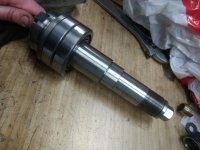
It took a bit more than a light tap to get it apart but I used Schaublin appropriate force and asked nicely in German, French, and Italian (sorry no Romansh). So now I have it apart other than the lower two bearings. I can't see a good way to get those off without damage? I would like to apply force to the inner race but can't see a good way to access that which is strange as you are supposed to re-lube the bearings, not just replace them. Maybe a hammer tap on the end and good old inertia will be enough but they seem more stuck than that.

I am sure there was not enough preload applied when I took it apart (as it clearly had play let alone being tighter than that) it may be that I can clean and relube the beaings, reassemble and be good to go but we will see. I have the upper bearing soaking in white spirits to clean it of grease as it seemed like the most likely candidate for failure. (not due to loads but because of the source of the sound and the fact the finish from is perfect when I use the head) I wonder if it isn't the fact the ejector is missing so I (and previous owners) have been tapping the draw bar with a hammer to remove tools from the spindle.

As always the parts are simply exquisitely made, if nothing else. We also have another one of Ola's favorite DIN 32711/32712 Polygonprofil to keep the gear in place. I was expecting a key etc but really this is a much more elegant and more robust way to keep the gear locked to the spindle.
IMG_20180107_203403161.jpg

Luke
 
I have the upper bearing soaking in white spirits to clean it of grease as it seemed like the most likely candidate for failure. (not due to loads but because of the source of the sound and the fact the finish from is perfect when I use the head)

It would take a seriously dammage bearing to make such a noise ( I seem to recall we already discussed the subject and you metionned hearing protection). I wish it was "only" a bearing problem for you, but I bet you'll discover the culprit is the -straight- bevel gear.

I'm sure there are more than a few 13 owners who'd trade the elegance of all the polygons on earth, for a good set of spiral bevel gears....:nopity:
This is a different sort of noise than those straight cut gears, it comes and goes, is high pitch and generally sounds like a bearing.
L
 
My german isn't amazing but I think it says that once I have the tensioning nut off (13.10.208) a light hit with a "fiber hamer" should remove the bearing assembly.

Minor correction, it says "Schläge" which is the plural, meaning "light hits" rather than "a light hit".

For reassembly it says, "Die Kugellager der Vertikalspindel erfordern eine Vorspannung. Bei ausgebauter Spindle werden sie vorerst durch Abstimmen des Distanzringes (13-10.215) spielfrei eingestellt. Um die gewünschte Vorspannung der Lager zu erhalten wird dieser Ring anschliessend noch um 1/100 mm gekürzt". I think means that to to get the correct tension the spacer ring (which is under the top bearing) needs to be shortened by 0,01mm after there is no play. This I assume will be more clear when I get the whole thing apart. I am guessing this preload should be easy enough to calculate from the pitch of the tension nut. (I think it is something very fine, around 1mm pitch) so so 3,6 degrees of rotation to the nut which isn't so very much. Can anyone add to this?

From looking at the diagram, it appears that the part 13-10.215 is a spacer ring. So then, based on the way this is phrased, I would have interpreted this to mean: surface grind the ring 13-10.215 thinner until there is no play. Then surface grind off another 0.010mm. But I'm not good at reading drawings, so this might not make sense.

Cheers,
Bruce
 
thanks Ballen, grinding down the ring does make more sense as it isn't going to compress. Before opening it I thought it might be some sort of spring etc but it is simply a ground steel spacer. Once I track down a correct bearing I will figure out a way to gind it (or porbaby hard turn the ring with CBN). It looks like Schaublin specially sourced the P4 grade bearing in this size as the big guys (SKF, ********* etc) don't produce it. I have a email in with what I think is the parent company of SRO in switzerland so maybe they will have a suggestion. I can get a P5 which would probably be just fine.

Luke
 
thanks Ballen, grinding down the ring does make more sense as it isn't going to compress. Before opening it I thought it might be some sort of spring etc but it is simply a ground steel spacer. Once I track down a correct bearing I will figure out a way to gind it (or porbaby hard turn the ring with CBN). It looks like Schaublin specially sourced the P4 grade bearing in this size as the big guys (SKF, ********* etc) don't produce it. I have a email in with what I think is the parent company of SRO in switzerland so maybe they will have a suggestion. I can get a P5 which would probably be just fine.

Luke, if you can carefully measure the end play and determine how much needs to be ground off the ring, just mail me the ring and I'll surface grind it and send it back. Hard turning this is unlikely to leave the faces parallel, so not a good idea IMO. Cheers, Bruce
 
thanks for the offer Bruce, I was going to turn a flat faceplate in place, glue the ring to it and then hard turn it but I can get a friend or two locally to grind it if that is the best way. It seems like a process that will take a couple iterations to get right so being able to do it in shop is appealing.

Luke
 
Grinding it would be better. You should be able to do it in a single pass, if you can measure the end play carefully. You remove that amount plus ten microns from the thickness of the ring. Grinding something that size parallel and to within a micron is trivial with a surface grinder, the hard part is to measure the end play accurately.
 
Hi Peter,

Nothing within a micron is trivial

OK, two microns then.

With a washer this size (probably 50 mm diameter or so and a few mm thick), a calibrated gage blocks, and a mikrokator, it's not hard. Temperature control is an issue for thicker things but these are thin enough that it doesn't make a difference. And even if the chuck is off by 5 microns over the entire surface, it will not be off by much over the 50mm diameter patch occupied by the spacer.

In practice, bring down the surface grinder one micron at a time until you touch off, then drop down the remaining number of microns.

Cheers,
Bruce
 
Last edited:
Trivial or not, I also have a surface grinder, if you prefer the easy access. Remember that if grinding a ring to the nearest micron is difficult, turning it, even with CBN, is worse. And controlling the runout and mounting flex of a disc in a lathe is a nightmare.

Ole
 
Trivial or not, I also have a surface grinder, if you prefer the easy access. Remember that if grinding a ring to the nearest micron is difficult, turning it, even with CBN, is worse. And controlling the runout and mounting flex of a disc in a lathe is a nightmare.

I agree with everything you said, but one thing you have written is a bit misleading. Luke is NOT going to give you the spacer thickness to a micron. Reproducing that might not be trivial (although not hard with gauge blocks and a good indicator). Luke is going to give you the delta, the amount to remove. Suppose it is 16 microns. If your surface grinder is calibrated in microns, bring it down until you touch the spacer, then 16 microns more and you are done. So the absolute thickness of the spacer never enters here.
 
Touch the spacer ????
Where
Left right in the middle front back Where does it touch
How parrallel is it initialy Is your grinder up to temperature
Did you resurface the magnet And clean clean clean
And then once more clean
 
Bruce: Yes, of course, sorry for the misunderstanding. Peter: I do in fact have a Jones & Shipman 540 in pristine shape with a freshly ground chuck, as well as a set of gage blocks and some other implements (!) Luke: Just bring the whole assembly, and we will figure it out.

Ole
 
Hi Peter,

Touch the spacer ????
Where
Left right in the middle front back Where does it touch
How parrallel is it initialy

This is from a Schaublin, so I assume that the spacer has been ground parallel to within a micron. Even if it is not flat, the magnet will pull it down flat. But obviously Luke should check with a micrometer that the two faces are the same separation all around the spacer.

Is your grinder up to temperature

Yes, I warm it up. Although for a piece which is this small and which can be ground in a minute or two, it doesn't matter, because the grinder doesn't grow/shrink so quickly.

Did you resurface the magnet

If the piece was long or large, this would be important. But here I would not bother, I would just check with a millimess that a 50 x 50mm region had not shifted since the last time that I dusted the magnet.

And clean clean clean
And then once more clean

Yes, absolutely, stone and clean, and clean again! And dress the stone.

Cheers,
Bruce
 
For a job like this i will often turn up a "dummy" spacer..aprox same size and thickness.....
Warm up spindle,dress the grinding wheel, set the dummy on the grinder table. Take a reference cut to just clean one side, turn over and surface the opposite side.....Grind close to starting height of the real part (use depth mic)
Leave the grinder height set.
Remove the dummy and measure the thickness......hopefully its slightly thicker than the real part starts out if you did your work carefully.....
Set real part on the chuck in the same position as the dummy was cut (magic marker) , cut to required thickness gauging from the true height of the "dummy"....

I also lap the reference side of the real part before placing it on the grinder chuck.....
Cheers Ross
 
Thnks Ross,that sounds like a good approach. I will give it a try.

I did a test hardened spacer on the lathe and while it looks great it isn't remotely parallel :)
I will go grind the real thing it at Ole's.

Maybe I could do it with a mag chuck on the lathe but I am not sure the cutting forces are low enough for that to be viable on a small part like this. (the ID on the test is 20mm) I thought the super glue method would work better than it did, I might have done something wrong but I don't think it is going to work no matter what.

IMG_20180110_112216669.jpg

Luke


Back
Top