What's new
What's new

Thiel Duplex 158 vertical head spindle bearings

kwijibo99

Plastic
Joined
May 4, 2010
Location
Melbourne, Australia
I was working on a milling project yesterday when the spindle bearings in the vertical head of my Thiel Duplex 158 began to consume themselves.
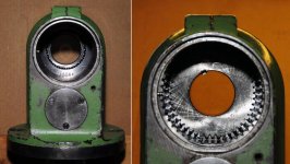
The lubrication on the Thiel vertical head is a total loss system so before running I usually give a few pumps of oil to the different lubrication points and a few drips come out through the bottom of the spindle every now and then during use. The first indication that something was not right was when it caught my attention that the oil drips were not the usual clean oil colour but much darker bordering on black, I gave them a quick wipe and made an alarming discovery:

Thiel Spindle Bearing 01.jpg

The spindle did not sound noticeably noisier than usual when running at higher revs but spinning it by hand it did feel a little bit lumpy where it was usually perfectly smooth. I removed the head and began to strip it down for a closer look at what was going on. My concerns that the gears might be damaged were soon alleviated as they all looked perfect. The intermediate shaft bearings and as best I could tell the upper spindle bearing all appeared to run smoothly by hand and there were no metal chips anywhere to be seen, although there was grease which I'm pretty sure shouldn't be there.
I removed the quill which contains the lower spindle bearing and it definitely felt slightly lumpy when turning by hand so I suspect the lower spindle bearing is the source of the problem.

The issue I have now is that I have not been able to remove the lower spindle bearing retaining ring. I replaced the quill in the head and removed the small locking screw then made up a pin spanner which I hoped would do the job but the retaining ring is much tighter than I expected and I have not been able to budge it. The holes in the ring showed signs that it had been tinkered with before as there was a bit of distortion which I peened back to as close to original as possible before they got any worse.
Before and after peening the holes.

Thiel Spindle Bearing 02.jpg Thiel Spindle Bearing 03.jpg

Looking at a drawing of the head it looks like this ring retains the lower bearing and also acts as a labyrinth seal.

Thiel Spindle Bearing 05.jpg

Given that the top retaining ring was only firmly hand tight (and a right hand thread) I thought the lower ring would be similar but it stubbornly resists any attempt to remove it either clockwise or anti-clockwise.
I am guessing that the presence of a locking screw indicates Locktite or similar is not usually used in this situation.
Part of the problem is I don’t know if the thread is right or left handed and so have not wanted to apply a large amount of force in either direction. If anyone has worked on a Thiel or something similar and can offer any advice it would be most gratefully received.
Cheers,
Greg.
 
I have a Thiel 159, but I can't give you any first hand advice for your 158 because the head designs are just too different. There were quite a few 158s in UK, so there is a chance that someone who reads this site will have direct experience. As far as I know, Thiels were not sold in the USA.
The manual for the 159 does describe how the vertical spindle should be removed for lubrication, and there are no special warnings for left hand screws etc. But the 159 uses SKF 'NN' type high precision bearings and I can see from your drawing that the 158 spindle bearing design is radically different.
 
Hi Bill and thanks for the reply.
I have managed to get the lower retaining ring loose and will continue to strip it down after consulting a mate of mine who is a machine spindle expert.
For the record it was a right hand thread.
The 158 head uses UKF UK series bearings, UKF Angular Contact Ball Bearings.
I haven't worked with these before so it might be interesting.
Cheers,
Greg.
 
Those bearings look fairly exotic, but then Thiel typically selected the very best available bearing design available at the time. I have the SKF spindle bearing book which describes in great detail how to set up spindles properly (159 design) using their bearings. That is not much use for your rather unusual bearings,so you would be doing the rest of the community a big favour if you document how you sort out your head - including new bearings (if you need them - hopefully not).
 
I have finished rebuilding the head and as Bill suggested it might be of interest as a reference to others down the track, I took photos during the process.

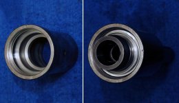
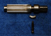
The components that make up the input shaft assembly.

Thiel Spindle Bearing 14.jpg

The reassembled input shaft assembly.

Thiel Spindle Bearing 15.jpg

My supplier managed to track down a new old stock bearing from somewhere in Germany which worked out to be a bit more than half the price of a new one from the local UKF reseller. I don’t know where they tracked it down from, it’s been around for a while because the box is marked “Made in West Germany” but I’m glad they managed to get one.

My mate (Machtool on this forum) managed to get the original bearing back to a more or less serviceable state by giving it a good clean and running it through an ultrasonic cleaner. As this is the first time I’ve worked with high precision bearings I figured a safe path would be to rebuild the head using the old bearing first even if the Thiel spindle is pretty foolproof as far as assembly goes. This way if I do happen to get something wrong it should become apparent without rooting a $600.00 bearing.

This is the spindle to which the bearing in question is fitted. It locates on the surface to the left and is retained by the threaded ring in the middle. The drive gear mounts in the upper spindle bearing which is fixed in the head cap and is retained by the ring to the right. The spindle shaft is free to slide up and down inside the drive gear as the quill moves in and out.

Thiel Spindle Bearing 17.jpg

Here the lower spindle bearing is installed and the quill housing and retaining ring is shown below it.

Thiel Spindle Bearing 18.jpg

This is a view of the quill before and after inserting the spindle. Getting the spindle installed was a bit fiddly as everything has to be lined up right for the bearing to go in smoothly. Any slight misalignment and everything locks up.

Thiel Spindle Bearing 19.jpg
 
Last edited:
The quill and spindle assembly.

Thiel Spindle Bearing 20.jpg

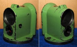
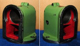
The head casting and the head cap with all grease and old oil cleaned out.

Thiel Spindle Bearing 21.jpg

Some more views of the head casting from different angles.

Thiel Spindle Bearing 22.jpg Thiel Spindle Bearing 23.jpg Thiel Spindle Bearing 24.jpg
 
The transfer shaft and a view of it installed in the head.

Thiel Spindle Bearing 13a.jpg Thiel Spindle Bearing 25.jpg

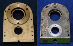
The head cap in which the upper spindle and transfer shaft bearings are mounted. Strangely the head cap is an aluminium casting with steel sleeves for the bearings.

Thiel Spindle Bearing 26.jpg

View after installing the head cap with the input shaft ready to go in. The input shaft must be installed with the little oil hole towards the top so it lines up with a mating grove in the head casting to allow oil to reach the input shaft bearings. This is probably the one part of the assembly that you could get wrong if not paying attention. To the right is the input shaft installed, the 66 is the last two digits of the machines serial number and many of the parts are so marked.

Thiel Spindle Bearing 27.jpg
 
This is a photo looking up into the head where the quill goes. You can see the upper spindle bearing and the transfer gear towards the bottom of the left hand photo. The right hand photo shows the spindle drive gear installed. Every gear is marked with the alloy it’s made from (16Mn Cr5) a part number and what I think is a date, some of these are just visible in the photo. The bevel gears have additional markings which I think might relate to inspection.

Thiel Spindle Bearing 28.jpg

The top of the spindle drive gear protrudes out of the top of the head so the upper retaining ring can be installed as seen to the right.

Thiel Spindle Bearing 29.jpg

This is the shaft which controls the quill movement. I plan to make a new one of these at some point with something a bit more user friendly than the simple square shaft for a handle.

Thiel Spindle Bearing 30.jpg

Some photos of the quill going in, the quill is a very precise fit in the casting and needs line up with both the bore and a keyway to get it in. This is a bit fiddly when your hands and all the components are covered in oil but in the end was a fairly painless operation. The quill is only retained by the quill control shaft and the clamp ring visible in the lower right photo.

Thiel Spindle Bearing 31.jpg

All back together and on the machine ready to continue with the job I was working on when I first noticed the problem.

Thiel Spindle Bearing 32.jpg

As mentioned all grease has been cleaned out of the head and after pumping in new oil I noticed a lot more came dripping out past the spindle when I first ran it than did so before. After about five minutes running at various speeds the dripping greatly reduced to the point of nearly nothing and everything seemed to be running smooth and a bit quieter than before.

I had previously contacted UKF who sent me some information on lubrication of their angular contact bearings in general. The bearings can be lubricated with either oil or grease depending on application. Most of the information pertained to circulating oil systems and atomizers. It states “With minimal Oil Lubrication, very small quantities of suitable oil are adequate, but it must be carefully distributed, to ensure that the oil moistens the balls and the grooves” and the figure of 1ml/hour per 25mm of bearing diameter is quoted as a generally recommended figure.

The Thiel manual recommends lubricating the vertical head with 7.5 to 8.5E (ISO68 as best I can tell) oil once a week, so based on this I’m guessing that the design of the labyrinth seal will hold enough oil to provide lubrication and allow any excess to pass through hence the initial leakage. I’ve always given each of the oil points a pump of oil before use so I’ll stick with that for now and see how things go.

I used the mill for a good four hours yesterday and it worked fine with no sign of trouble so I’m a happy camper. I’ll continue to run it with the old bearing for now and just play it by ear. Now that I know what’s required I reckon I can strip the spindle and replace the bearing in around an hour without too much trouble.

Many thanks to Phil (Machtool) for his invaluable assistance and advice.
Cheers,
Greg.
 
Thanks for documenting that so thoroughly. As I expected, the internal design is different to my 159 head with the built in boring gearbox etc, but there is a family resemblance to some of the parts as you would expect.

It is a testament to the original design and manufacture that everything looks to be in good condition internally - the gears in particular. I have noticed in my Thiel that many of the gears are marked, not just with part numbers but with other useful information, presumably to help with replacement if it was ever required.
 
Greg,

I'm a Deckel owner so this is only of general interest to me, but I think it will be of great value to anyone who needs to work on a 158 vertical spindle in the future. The photos are very well done, and a real service to other 158 owners.

I am curious about one point. Your first report showing black oil on a towel also showed metal shards or fragments, which I assumed were from a bearing that was self-destructing. But you said that your friend was able to restore the bearing back to usability. What did he need to do? Where did those metal bits come from? What part of the bearing was damaged?

Cheers,
Bruce
 
Hi Bruce,
The bottom spindle bearing was indeed the source of the iron fragments. When the bearing was removed it was definitely lumpy when turned and the oil inside contained small metal particles.

It was given a good flush with kero in a parts washer, blown out with compressed air then given fifteen minutes in an ultrasonic cleaner. This process basicly cleaned out all of the metal particles and allowed the bearing to spin much more freely albeit still not quite as smooth as a new one.

Using a loupe to have a close look at the bearing you could see fine pitting on a number of the balls which was the source of the filings.

When the problem first occurred I stopped the machine as soon as I noticed it and I think this might have limited the damage. With the floating particles removed the bearing will not be grinding itself away and seems to be serviceable for now. Using the old bearing is not a permanent fix, it was more a trial for me to put the head back together and have everything working without risking potential damage to the new bearing.
Cheers,
Greg.
 
Hi Greg,

I would think that once the bearing balls are pitted, their days are numbered, because when those pits roll on the races, their edges will fracture off, creating more grit and further abrading the bearing raceways. In your shoes, having practiced the procedure and purchased a replacement bearing, I would not wait to swap it. If the current bearing fails it may do other damage, either to the machine or to whatever you are working on at the time.

Cheers,
Bruce
 
Fatigue fracture leading to pitting, like potholes in a roadway, are the normal end-of-life failure mechanism for rolling bearings. Excess preload, contamination, and corrosion can accelerate the process. I would want to be sitting down when I asked the cost of a new set of those odd-ball bearings. Will a pair of normal angular contact bearings fit in the same envelope?


Back
Top