What's new
What's new

Punch/Die - What corner radius on punch or die in unspecified sharp corners ???

SeymourDumore

Diamond
Joined
Aug 2, 2005
Location
CT
Guys who cut stamping dies for a living, I have a question.


When you design and cut a punch/die with unspecified corner radius for a finished part ( like sharp, but not actually called out as such ), what clearance do
you allow in the corners?

Case in point ( and while I do wirecut as part of my operation, tool and die is less than .01% of what I do... ), I have to make a punch and die set for a part
that is a .075 x 4.05 rectangle out of .022 thick material.
It is my part and I really do not care how sharp the corner is, just somewhat there.

So, assuming a 10% clearance, I've cut the punch to be .071 x 4.046 and gave it a .007 corner radius ( because .01 wire is what I use )
The punch is within .0003 total in both of those dims, no problem there. I can't measure the radius, but I am assuming that they are there as well.

But now, I am cutting the punch holder and in this thickness and shape I want it to be dead nuts, just under press fit.


I've got both sides ( the .071 and the 4.046 ) just right, the punch fits in both directions independently, and yet, it does not freaking go into the holder!!!

Please do not flame me for asking a really stupid question, but what radius would you use for a punch in this instance when the wire is .010?


Oh, why this is important ... Because I was a dumbass and wanted to cut all three ( holder, stripper and die ) in one setup.... :dopeslap:
 
In an unspecified "sharp" corner like that ...

For the punch and die, we use .005" external radii and program "sharp" on internal corners.

Your not going to get a sharp internal corner, .010" wire will produce near enough to a .005" internal corner with skim passes and your punch/die clearance will take care of the rest there.

On the punch holder and stripper we clear the internal corners unless they are absolutely necessary, which isn't very often.

You shouldn't need a press fit on your corners/corner radii.

However, the way you did it should have worked.

How many skims did you use?

Did you program a sharp internal corner?

If that won't work try a .010" radius on your punch next time.

This time, just stone the corners enough to get it in the punch holder.

... when you cut 'em all together like that; how do you get a press fit in the punch holder, slip fit in the stripper, and the proper clearance in the die?
 
B

I"ve skimmed 4 times, and the numbers I need are dead-on.
It is the corners that need some putzing with now, but stoning is the first step.

As far as how I've planned the cut is that the die and the stripper is bolted together on the lower side, the holder is then bolted through
separately on top.
This way when I've cut all the features along with the dowels, they are unquestionably in the right place.
Then the first cut for the holder is .002/per side under to accomodate the punch, then I remove the holder and cut the die/stripper in place at the same time/same size.
 
Well, first off, a 0.071 punch isn't going to make a 0.075 hole. The punch determines the hole size, otherwise you wouldn't need a stripper. Your punch needs to be burned nominal. If you want good fit with the punch holder you burn 0.0002 per side over. This usually ensures a fit that is tighter than slip fit, but not as tight as press fit. In other words, with some care and a copper hammer, it will go.

Secondly, what are you cutting with this? Your material plays a HUGE role in your die clearance. For common soft steel, you want 10% PER SIDE, not total. For stainless like 304, it's 15% per side. Not enough clearance causes the steel to coin before breakout and makes an ugly hole.

He's blanking a part from .022" SS.

Several sources recommend 20% total for SS.

Therefore he's made his punch .004" u/s, which ought to be close enough.
 
SeymourDumore,

You have the correct per/side reduction between your Die and Punch for the 0.022" thick material you want to stamp. Out of curiously, how thick is your Die Plate, and did you put any die relief on the bottom (say a 0.2" straight land with a 1 degree back taper)?

As for your Punch Holder, what you did in practice isn't wrong, but it’s the Sharp Corner geometry that is causing you a problem. I always modified my Punch Holder geometry and made the corner radii 0.0005" ~ 0.001" smaller than the Punch so that I would eliminate lock-up in the corners. This made the die assembly process much easier, and having the geometry features all 1:1 to each other really doesn't improve anything on the stamping die...especially on a rectangle where you have plenty of bearing surface on the X/Y faces. Processing the Punch and Punch Holder geometry 1:1 is OK if you have some really small geometry features that have minimal surface area for alignment (say an odd-ball shaped part with no flats).

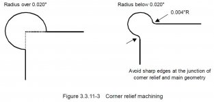
In theory, everything you did should have been fine, but did you process the Punch Holder with a “zero” radius? Even with a programmed sharp corner, you will get about a 0.006” radius in the corner, which is a combo of the Wire radius (0.010” in this case) plus some overburn. I think the easiest thing for you to do at this point is to break out a stone or die grinder and dust off the corners on the bottom mating section of the Punch. If you need to process something like this again in the future, you can Dog-Bone out the corners of the Punch Holder to eliminate them as an interference area (this is commonly done to the Punch Holder). Take a look at the attached picture on Corner Relief... Corner Relief.jpg

-Brian
 
B

I"ve skimmed 4 times, and the numbers I need are dead-on.
It is the corners that need some putzing with now, but stoning is the first step.

As far as how I've planned the cut is that the die and the stripper is bolted together on the lower side, the holder is then bolted through
separately on top.
This way when I've cut all the features along with the dowels, they are unquestionably in the right place.
Then the first cut for the holder is .002/per side under to accomodate the punch, then I remove the holder and cut the die/stripper in place at the same time/same size.

While not my preferred method, we have done it that way.

As for the corner interference:

After one too many "should' worked" experiences we do this whenever possible:

Corner Clearance.jpg
 
Yupp, the " Seemed like the good idea at the time" is quite appropriate...

I've made the outside corners to be .007 for exactly that reason, knowing that it won't make a difference in the finished part and is "going to work just fine" in the holder.
Yes Brian, I did leave all inside corners as sharp, but since dogbone is out of the question right now, I think the stoning is the way to go.

BTW, the die and holder is 1", and the die is relieved from the back to give a .250 land, basically it's just a milled pocket from the bottom.
The finished part is not EXACTLY a rectangle, it actually has a .025 tab on both sides, hence it was easier to mill out the bottom rather than taper cut the relief
and risking burning into the cutting edge in the narrow portion.
 
He's blanking a part from .022" SS.

Several sources recommend 20% total for SS.

Therefore he's made his punch .004" u/s, which ought to be close enough.

So, the holes you punch end up being bigger than the punch? Where do you buy your steel?
 
Also, just a tidbit here for next time, maybe. On an older (mid 90's, not sure if it went away on later models) Charmilles wire edm that has the conversational, (not sure what it is actually called) it has a feature to undercut corners to clear them. It will make a "loop" at the corners. I know with cad/cam it is fairly easy to just design this into your part, but sometimes you get comp issues if your clearance isn't just right.
 
So, the holes you punch end up being bigger than the punch? Where do you buy your steel?

Punch determines hole size.

Die determines part size.

You need the proper clearance either way.

He's blanking a part through a die, therefore the clearance must go on the punch.

If he made the punch to size and put the clearance on the die his parts would be .004" oversize.

(edit)

And:

Your hole can actually be smaller than the punch and you part larger than the die.

To be even more technical, since the initial phase of the punching/stamping process causes a thinning of the material and consequent lateral compression/expansion, for really close tolerances you have to account for this and make your punches larger and dies smaller to account for the snap-back ...

Material, material thickness, and punch/die clearance and shear (if any) have a great effect on this.
 
Last edited:
Yupp, as B said, my part is the "slug", so die is what gives the size.

Now, to the issue I've had .... ( Yes, the punch is now nicely in the holder and the tool is working with a piece plastic test cut, will be installed in the dieset tonight with the real material )
Turns out that it was not necessarily a bad idea to cut all three at the same time, but Seymour deserves a serious slap on the head for his lazy attitude! :dopeslap:

Here is why the thing didn't go together:
I have made ALL the programs from the very same geometry, except padded the offset to get the required size.
That is the punch was padded -.002 in the control, while the holder was +.002.
So guess what happens with that thinking when the outside corner radiuses are programmed to be .007?
Yupp, correct guess, it becomes .005, that is it get's to be too sharp!

Anyway, a bit of stoning did take care of it, albeit it was not all that easy to do in the holder with only .075 width.
 
Good info here. I realize this thread is a couple years old but wanted to mention espritcam does those corner reliefs automatically for you. Has several different profile types to choose from and you can control the sizing and whether you want blends.


Back
Top