What's new
What's new

shop built leveling fixture

zoiezeus

Plastic
Joined
Mar 4, 2015
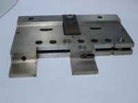
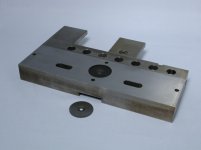
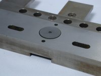
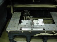
Im somewhat of an EDM novice, 4-5yrs, have alot to learn yet, I dont do alot of wire work normaly at our shop, but at times i get a group of parts that need burned. I have a good newer machine but i never totally convinced the boss to invest in a fixturing system, a $5-$6 thousand system did seem too much for a $140,000 machine, but it is what it is. I normally have flat bar stock that are just clamped flat to the table and no fixture is needed. But the need for a leveling system comes up time and again. Im confident I can make one, in shop, that will serve my purpose. I have an idea for one that i think will work good. I'm going to try to explain my concept as best i can and would like any feedback or opinions anyone may have. Disregarding any specific dimensions or material type this is what Im thinkin. I'll throw out some dims just for perspective. Two plates 5"x7" 3/4" thick, machine a spherical pocket with 1/2" radius approx 3/8" deep into the center/face side of both plates. Now a 1" ball bearing can be sandwiched between plates. The bottom plate would simply clamp/bolt to table. The top plate will have holes for 4 set screws and 4 shoulder bolts. Four thru holes, oversized for clearance around shoulder bolt, one in each corner, tapped hole in base plate cooresponding each bolt. Now I have btm plate with recess facing up and top plate with recess facing down a 1" ball in between as a pivot point. In between plates at each bolt hole is a die spring plus a die spring on top of top plate at same locations. A proper length shoulder bolt goes thru top spring, top plate, bottom spring, and threads in to base. Now top plate is suspended with spring pressure but can rotate/pivot on ball. Top plate will also have 4 tapped hole at the centerlines of X and Y between shoulder bolts. So , say the sh bolts are at (X,Y).. (-3,2)(-3,-2)(3,-2) AND (3,2). Tapped holes would be at (-3,0)(3,0)(0,3)(0,-3). A long set screw will thread into each hole of top plate down to base. Now to adjust top plate for level, turn set screws in/out accordingly applying more or less spring pressure to plate moving it up or down. The spring pressure will have to be balanced so that the ball/pivot is always pinched tight between plates but top can also tilt as needed. I hope most of you followed that, and the big question do you think it will work. Thanks for any comments in advance.
 
Three of these will do the job quite well with a lot less work:

http://www.gaiseredm.com/Catalog/ExtendableClamp.html

We have 4 sets of three.

Most used tooling in our EDM dept.

(edit: read (at) post)

That's a whole lot of work for not much, if any, gain.

Just how "level" do you need to be?

How parallell are your parts to begin with?

The fixtures I linked, or shop built versions of same, will be much cheaper and/or easier to make.

Additionally, you have not specified how you plan to mount/attache your workpiece to this device ...

If you absolutely have to be that level, pony up and buy the tooling.

If you insist on making this yourself:

Hard to tell from your post but it sounds like you will have four leveling screws?

You will be chasing "level" with that all day and be no closer than when you started.

Ditch one of them and go with a three-point system.
 
Last edited:
Sounds like it would work but separating the two planes would be an improvement...your way, if I understand it correctly, would not allow independent leveling of the two planes. If you correct in one plane the other would be affected, right? A three plate setup with two balls making a line of pivot would be easier to level.
 
Hi zoiezeus
Here's what I built years ago, to do almost exactly what you have described but with a built in vise attached.
(Sorry about the crappy photography)
It's very simple, much simpler in construction than what you've described.
Basically it's a ball with a big flange around the equator; big enough to make a vise body from.
A ball socket is placed below it and another is placed above it.
The upper socket is integral to a cantilevered arm that comes in from the back side of the fixture and acts as a very stiff spring.
A single socket head cap screw provides the loading force, also from the back side of the fixture.

The upper socket is forced down onto the lower socket with the flanged ball between them.
Four adjusting screws at the 12:00, 6:00 3:00 and 9:00 positions will allow me to level the part around the X axis and the Y axis separately.
Two additional adjusting screws coming in from the side allow rotation around the Z axis.

The fact that you can adjust any axis independently of the others makes this system much easier to use than those based on 3 points of adjustment, and I can level and align to within a tenth very quickly and reliably, one axis at a time without disrupting the other two axes while I'm adjusting the third.

The additional benefit is that it all comes apart for cleaning very easily.
It's simple, it's strong and it's accurate.

So I recommend your design be similarly simple and easy to take apart.
I'd also go with four points of adjustment aligned so you can tilt around any one axis at a time.
Otherwise it'll be much harder to adjust and it'll fill up with EDM debris quite quickly and become impossible to use.
I built mine with the vise attached; you may choose to attach a separate vise or an angle plate or a rail; whatever you prefer.
Cheers

Marcus
Implant Mechanix • Design & Innovation > HOME
www.vancouverwireedm.com
 

Attachments

  • wire vise front view.jpg
    wire vise front view.jpg
    25.1 KB · Views: 362
  • wire vise underside.jpg
    wire vise underside.jpg
    107.1 KB · Views: 381
  • wire vise swivel base.jpg
    wire vise swivel base.jpg
    97 KB · Views: 344
  • wire vise rear oblique.jpg
    wire vise rear oblique.jpg
    101.6 KB · Views: 340
  • wire vise front oblique.jpg
    wire vise front oblique.jpg
    97.6 KB · Views: 295
Hi zoiezeus
Here's what I built years ago, to do almost exactly what you have described but with a built in vise attached.
(Sorry about the crappy photography)
It's very simple, much simpler in construction than what you've described.
Basically it's a ball with a big flange around the equator; big enough to make a vise body from.
A ball socket is placed below it and another is placed above it.
The upper socket is integral to a cantilevered arm that comes in from the back side of the fixture and acts as a very stiff spring.
A single socket head cap screw provides the loading force, also from the back side of the fixture.

The upper socket is forced down onto the lower socket with the flanged ball between them.
Four adjusting screws at the 12:00, 6:00 3:00 and 9:00 positions will allow me to level the part around the X axis and the Y axis separately.
Two additional adjusting screws coming in from the side allow rotation around the Z axis.

The fact that you can adjust any axis independently of the others makes this system much easier to use than those based on 3 points of adjustment, and I can level and align to within a tenth very quickly and reliably, one axis at a time without disrupting the other two axes while I'm adjusting the third.

The additional benefit is that it all comes apart for cleaning very easily.
It's simple, it's strong and it's accurate.

So I recommend your design be similarly simple and easy to take apart.
I'd also go with four points of adjustment aligned so you can tilt around any one axis at a time.
Otherwise it'll be much harder to adjust and it'll fill up with EDM debris quite quickly and become impossible to use.
I built mine with the vise attached; you may choose to attach a separate vise or an angle plate or a rail; whatever you prefer.
Cheers

Marcus
Implant Mechanix • Design & Innovation > HOME
www.vancouverwireedm.com

Pure genius Marcus.

... how much for the prints?
 
Wow very impressive leveling fixture Marcus ! Have you built any attachments for this like Vee -block setup , or claw ? I've been working on something but not quite as sweet as this. Thank you for sharing !
 
HI JTB3:
I made the front of it with a tee slot running down the center of the front face, so if I want to, I can just bolt a plate or a vee block or whatever directly onto the front face and then use the tilt mechanism as usual.
In fact, I'm running a job in the next couple of days where I've got stacks of plates I've laser welded together, then bolted to a block that I bolt to the front of the vise.
I level the plates with the gadget and then wire cut a bunch of arms for a medical device from those plates.
Once I set it up, I'll snap a couple of pictures so you can see how it works.

I also quite commonly will just squeeze a vee block in the vise and then clamp my stock in the vee block and adjust is as I need to.

A last thing; I spent an enormous amount of time lapping it as square as I could make it; that's because I often don't bother with the tilt adjustment and just bolt the vise directly to the machine table.
It's accurate enough that if my stock is square, I'm typically within 0.0002" in 6" which is already pretty decent for a lot of parts.
If I need better, it's simple to just re-mount the vise with the tilt mechanism in place and then dial it in, but I do that probably less than 10 times a year for the really fussy stuff.

Cheers

Marcus
Implant Mechanix • Design & Innovation > HOME
www.vancouverwireedm.com


Back
Top