What's new
What's new

Home Made Edwards 55 Ton Ironworker Punch Push Feed System Build Thread

JidoukaSS

Aluminum
Joined
Jul 24, 2012
Location
Wisconsin, USA
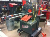
I originally posted this in CNC forum but this should probably be in the general metal working category. Anyways, I have a few jobs coming up that require me to make thousands of feet of custom track using an Edwards 55 Ton Ironworker, and there is no way I`m going to measure/mark every piece, so I started looking into options to fully automate this process. There are commerical options available, but what`s the fun in that right. I came across CNCRP Nema 34 Rack and Pinion system and it looks like it will do job.

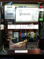
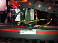
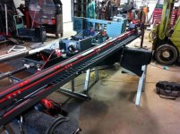
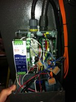
I plan to use the R&P running parallel with a roller table. I already have the control box which I put together for a 36in brake backgauge located on the other side of the machine. Now that I`m adding twice the control I wish I wouldn`t have used my e-scrap enclosure and just spent the 300 bucks on a 24x24x8 because as you can see from the photo, its a little full. Touch screen will be mounted on an extended swivel to go to both stations. I plan on putting a few pneumatic rams to control and lift work out of custom dies that don`t punch holes. Since this will be a PLC based control I was also going to add high volume air nozzles to clean off the R&P based on cycle times or just manually via screen. (cooler than brushes)

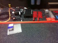
Finally started to get parts in, and I will try to document the build and update this thread.

Features I hope to have when completed:

Full control via touchscreen (PLC Based Control System)
Jog FWD/REV with relative move
Absolute move
Semi Auto User Job Recepie (with workpiece offset)
Full Auto User Job Recepie (with workpiece offset)

Pneumatics
Lift work out of custom dies
Dual high pressure air nozzles
1 each side on pinion to clean rack based on cycle time
 

Attachments

  • new4.jpg
    new4.jpg
    89.9 KB · Views: 1,672
  • new_004.jpg
    new_004.jpg
    92.5 KB · Views: 6,180
  • new_003.jpg
    new_003.jpg
    91 KB · Views: 2,522
  • new_002.jpg
    new_002.jpg
    96 KB · Views: 1,530
Progress Update

The backgauge is coming along, although it feels like it`s moving at a snails pace. I got alot of the mechanical work done and now I`m working on the electrical Aux I/O box which will interface to my main control box as well as the Ironworker and contains all the pneumatic controls. One issue I came across when assembling the motor mount was that my stepper motor shaft hit the rack clamps. I ended up having to make a motor spacer plate that raised the motor about an 1/8". Looking at the shaft length of the motors that Ahren sells compared to the Gecko 960oz/in motor that I bought, there is a difference. 1.18" motor face to shaft end on Ahren`s motor and 1.46" on the Gecko. Not knocking Ahren`s parts, there great, just a minor issue that was easily resolved. Check out the photos below. Details in photos.
 

Attachments

  • zzj_009Documented.jpg
    zzj_009Documented.jpg
    98.1 KB · Views: 1,207
  • zzj_014Documented.jpg
    zzj_014Documented.jpg
    95.9 KB · Views: 2,147
  • zzj_031.jpg
    zzj_031.jpg
    95.7 KB · Views: 897
  • zzj_037Documented.jpg
    zzj_037Documented.jpg
    89 KB · Views: 727
  • zzj_046Documented.jpg
    zzj_046Documented.jpg
    90.9 KB · Views: 908
Pinion Force

To maximize the life of the parts, I wanted to set the pinion force as light as possible to meet my needs. Using a formula I found the math comes out to be:

Nema 34 965oz/in at 2:1 = 1930oz.in
1930 oz.in / .5in (Pinion pitch radius) = 3860 oz
3860oz to lbs = 241.25lbs
241.25 x .364(Seperating force for 20 deg components) = 87.815lbs max pinion seperation force needed to produce 241.25lbs.

So Pinion Force= 0.364 x Desired Work Piece Force (Up to Max 241.25Lbs)

Max Force Lbs / Pinion Seperation Force on Rack Lbs

25 / 9.1
50 / 18.2
75 / 27.3
100 / 36.4
125 / 45.5
150 / 54.6
175 / 63.7
200 / 72.8
225 / 81.9
241 / 87.815

I plan to start out at 75lbs of force which is 27lbs pinion force. The only way I could think to measure that is wrapping a cable around the pinion and using a scale, pull until the pinion comes off the rack. I wanted to be semi-scientific about it but, like a lot of things, it might come down to trial and error.

I am I full of S@#% or will this work? What do you guys do?
 

Attachments

  • new_001.jpg
    new_001.jpg
    87.8 KB · Views: 666
Brake Backgauge

Before I started building the punch push feed table, I made a 36inch acme screw gauge for the brake section on the ironworker. I built it out of 80/20. Its cheap and that part of the ironworker does not see much use so it should hold up awhile. To save money I got the cheapest aluminum blocks on Ebay that I could find and milled/bored all of the parts. Bearing blocks have recessed radial bearing on one side and thrust washer/bearing on the other. The motor was little heavy for the 80/20 at 30in so I had to make a slotted support bar to level and help support the unit.

Both gauges use the same control box, all I need to do is plug in the sensors and motor. Eventually when I get a touchscreen I will be able to auto switch between workstations, simply by selecting which station your at changing the motion profile.

I'm not a machinist by any means, but I am building it because these gauges will save alot of time and I really like the control work that's invloved. Please by kind to my design.
 

Attachments

  • 0142.jpg
    0142.jpg
    93.2 KB · Views: 793
  • 0032.jpg
    0032.jpg
    93.9 KB · Views: 566
  • 019.jpg
    019.jpg
    94.1 KB · Views: 580
  • 004.jpg
    004.jpg
    93.8 KB · Views: 653
Another Progress Update

I got most of the electrical done. I found an electrical box plug that fit perfectly in the stepper motor to help keep the crap out. My E-Scrap Aux I/O box, with scrap terminal blocks, is done and tied to my main control box, R&P Gauge, and the Ironworker. I added a few relays to the ironworker tied to the up/down stroke sensors with one contact connected to where the sensors use to be and one contact as an input to the PLC (position feedback so I don't smash the punch) I'm also tied into the autocut circuit and can now control the punch with a click of the mouse. As you can see, the ironworker box is, for lack of a better word, a cluster@#$%. I added some relays but the ironworker essentially came that way; no prints, wire numbers, generally a mess. Thanks Edwards.

Well I finally got a hold of some conveyors locally saving a ton of money. I got two 10ft conveyors with 3in roller centers, 5 stands(although they don't go high enough), and 16ft of stand channel for $315.00. Would cost over $1000 delivered. The stands only go up to 24" so I have to fabricate to make longer ones. I also have to make a base with casters that extend past the center point of the backgauge which gets bolted to the side of the conveyor with 1545 80/20, so it doesn't tip. You know, it seems like everytime I save money, my workload doubles, (Control boxes, conveyor stands). Luckily labor is free right?
 

Attachments

  • zzj_055.jpg
    zzj_055.jpg
    97.5 KB · Views: 432
  • zzj_062.jpg
    zzj_062.jpg
    92.7 KB · Views: 565
  • zzj_065.jpg
    zzj_065.jpg
    92.5 KB · Views: 491
  • zzj_070.jpg
    zzj_070.jpg
    93.8 KB · Views: 454
  • zzj_075.jpg
    zzj_075.jpg
    97.4 KB · Views: 558
Well I got the other conveyor stand built and bolted to the conveyor. I'll probably have to square up the legs and either weld a piece of tubing the length of the table between the 4in square tubes or make a sliding tube bracket that I can adjust; something to keep the legs from collapsing. The rest of the 80/20 will be here this week and I hope to get everything put together and then torn apart to prime, paint, and clear coat.
 

Attachments

  • sdgsdfg.jpg
    sdgsdfg.jpg
    94.9 KB · Views: 1,073
Looking good. Not sure you need all those heatsinks on the motors as it should be a pretty light duty cycle. But Im looking forward to the video when you're done!
 
Looking good. Not sure you need all those heatsinks on the motors as it should be a pretty light duty cycle. But Im looking forward to the video when you're done!

Yeah I know it's overkill but I had a chunk of heatsink laying around so I used it. My Nema 23 gets extremely hot doing nothing, I was surprised that the Nema 34 stays as cool as it does; that coupled with the gearing, and almost no load to push the workpiece on the roller table, I agree that I don't really need it.
 
I have an older Edwards Jaws IV 50 ton machine, strictly mechanical control of the valve, no solonoid.
They are kinda crude, a bit over rated for capacity, but get the job done in general.
The control box 'mess' does not surprise me at all.

I realize you used the Edwards probably because you had it, but if you're not going to need to change a variety of tooling for the production job, a dedicated mechanical punch press would be faster and keep the Edwards free for other general job shop work.

Interesting project!

Waiting for the video....


dk
 
You also need good ear plugs for that Edwards 55!
I knew a guy that had one and the hydraulic wine would go right through me!
 
Any dedicated machine is usually much better than an all in one unit, but to cut machine cost and save shop space, the ironworker does have a place. I'm assuming they use the cheapest electrical parts to compete with the chinese machines, like the sensors and power supply from a brand I've never heard of and I thought I've seen them all. Now when it comes to their attachments, they are definitely try to make a profit. Like the AutoCut sensor. They want $750 for a $20 dollar sensor. Granted their quip grip stop would be nice, but I just bought a sensor and cable from Automation Direct, swap the leads in the cable to match their M12 box plug, and made a stop (though not as nice as theirs). Total cost $34.50.

As to the noise, yeah I wear earplugs when running just about everything. I'd rather go deaf listening to music than a machine.:D
 
Progress Update

--------------------------------------------------------------------------------

Well I finally got everything painted. I'm seriously thinking about not painting the take away conveyor. It's a serious pain since it's aluminum and galvanized metal which needs special primer that I have roll on. I have to rough up the metal and put 2 coats of primer and 2 coats paint. Though it's soul sucking I probably will (Being Type A really is a burden sometimes:wall:)

The conveyor stand has an adjustable support that keeps the stands from collapsing and the 4" tubes have 3/4" holes for 3/4" jack screws on non skid pucks. This gives the option to level or just put some weight on pucks to keep the roller table from sliding around. I also skipped two support feet because the cost is going through the "Expletive" roof.:eek:

Things Yet To Do:

Replace Registration Prox:
I started thinking about the repeatability of the prox switch that I bought from Automation Direct. Looking at the data sheet all the technical data I need is N/A. Which tells me it must be very bad. Since my step count is only as good as my starting point, I upgraded just that sensor with a much better Panasonic sensor that didn't break the bank and has a max error of .0016. The other sensors are just limits, so I don't care about their repeatability.

Ironworker Interface Plate:
I need to make a bracket that bolts on the end of the roller table and an interface plate that will be attached to the bottom of the punch pedestal. One, it will keep the conveyor rigid and two, it will allow the backgauge to be taken off the ironworker and put back on in the same place without having to massage the numbers everytime you need to use it.

Workpiece Pusher:
This one is going to take some thought. It needs to be adjustable for squareness to the rollers and the Ironworker. It also need to be adjustable for heigth to the rollers.

Program:
Easiest on the body, hardest on the mind. (What I'd rather be doing:D)
 

Attachments

  • 330.jpg
    330.jpg
    94.3 KB · Views: 566
  • 331.jpg
    331.jpg
    93.4 KB · Views: 1,794
  • 333.jpg
    333.jpg
    95.6 KB · Views: 627
  • 337.jpg
    337.jpg
    92.3 KB · Views: 745
  • 340.jpg
    340.jpg
    96.1 KB · Views: 710
Last edited:
I would seriously share all the details with Edwards!

They probably have customers or potential ones that would want such custom
attachments.
Could be some nice business there........

dk

I really don't think it's that good as is. Maybe as a prototype pitch?
 
More Pics

Here are some more pics with backgauge pushed up to the machine to give everybody a general idea what it's going to look like when finished.
 

Attachments

  • 057.jpg
    057.jpg
    96.1 KB · Views: 621
  • 061.jpg
    061.jpg
    97.6 KB · Views: 737
  • 064.jpg
    064.jpg
    92.6 KB · Views: 658
I really don't think it's that good as is. Maybe as a prototype pitch?

Yes I think it's pretty good when you color match the paint!
It's probably tooo good for what you're end goal is.....to make the parts.

I think the Edwards people would be very impressed or SHOULD be.
You could possibly be their 'turn key' department....IF you wanted to be and IF they are smart enough to "see" the potential of that....

Nice job so far.
 
Yes I think it's pretty good when you color match the paint!
It's probably tooo good for what you're end goal is.....to make the parts.

I agree that the trim and finish work is too nice for what it's doing but, form is as important as function to me. I know every scratch and dent is going to stick out like a laser beam in the eye (maybe a little touch of OCD:nutter:), but I'm going to look on it positively. Every scratch and dent will be a gauge of the equipment's success and hopefully be an indicator of, well, CA$H FLOW!
 
Small Progress Update

Not too much going on this week; a little burned out:Yawn:
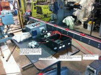
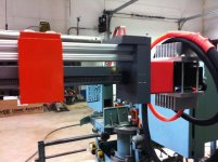
. I got the interface plate for the machine done. The control boxes also got mounted and I started roughing out the pusher bracket.
 

Attachments

  • 004.jpg
    004.jpg
    94.6 KB · Views: 1,507
  • 007.jpg
    007.jpg
    95.1 KB · Views: 642
  • 016.jpg
    016.jpg
    97.2 KB · Views: 864


Back
Top