EngineerTex
Plastic
- Joined
- Oct 31, 2016
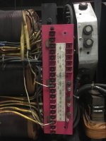
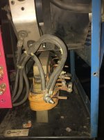
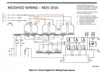
Lurked in the forum a while and converted a Miller TS250 welder to single phase about a year ago. It's worked great and I've had no problems with it. I have attached the series of photos of the conversion for how I did it. I followed the Haas-Kamp method as found on the Practical Machinist forums.
So now I want to make a change. I would like to use an SCR to control the voltage by a knob on my wire feeder, but I'm not exactly sure on which way to proceed.
I have a single-phase 10kW SCR that I can use in the system before the transformer and capacitors. It is undersized, since this system should run up to about 12kW, but should at least tell me if this will work. The question I am mainly struggling with is if I should completely avoid that and obtain a 3-phase SCR and install it between the capacitors and the transformer.
Any help, advice or berating is appreciated.
Thanks!
01 - Wiring as found:

02 - WYE Jumpers as found:

03 - Fan motor wires as found:

04 - On/Off switch wires as found:

05 - Delta secondary wires as found:

So now I want to make a change. I would like to use an SCR to control the voltage by a knob on my wire feeder, but I'm not exactly sure on which way to proceed.
I have a single-phase 10kW SCR that I can use in the system before the transformer and capacitors. It is undersized, since this system should run up to about 12kW, but should at least tell me if this will work. The question I am mainly struggling with is if I should completely avoid that and obtain a 3-phase SCR and install it between the capacitors and the transformer.
Any help, advice or berating is appreciated.
Thanks!
01 - Wiring as found:

02 - WYE Jumpers as found:

03 - Fan motor wires as found:

04 - On/Off switch wires as found:

05 - Delta secondary wires as found:


