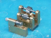
This thread may well have gone cold but we clearly have a common interest. I have built a Jacobs gear hobbing machine which starts as a set of castings from College Engineering Supply. I have adapted it to make helical and worm gears as well as spur gears. One of the items I have made is a double enveloping (or globoid)worm and wheel.
Nice
")
In case anyone is interested, the way these were/are made in production is a variation on the hobber theme. Michigan Tool built gear machinery and also made and sold the Cone Drive gearboxes. So they made their own machines to build them. Textron bought Michigan Tool when they went tits-up, and saved the double-enveloping Cone Drive product line.
Imagine a standard gear hobber. Put a large (same size as the wormgear) shaper cutter on the table. The teeth are thinner than standard. Put the worm blank where the hob normally goes. Feed the hob slide down onto the cutter mounted on the table to get your threads on the worm. Now the cutter on the table is advanced a ways, then retarded a ways to get the correct toothspace. Then the hobslide is moved up, hourglass worm removed, viola.
To cut the wormgear, similar idea. An hourglass-worm-shaped thin-tooth cutter placed in hob slide and fed into the wormgear blank radially, just like normal infeed wormgear cutting. Then the blank is advanced a ways, then retarded a ways, to get the correct geometry. Then the tooth space is big enough to withdraw the cutter.
They claim an advantage of these is higher loading but I don't see it. In order to assemble them the wormgear has to be split, assembled, then the teeth spread to contact the worm on both sides. So you only have half as much wormgear in contact, so what's the advantage ?
For low-backlash tho, they seem to work well. The Michigan hobbers used double-enveloping worm sets to drive the table. And at least one high-power gear gasher uses them to drive the cutter, so no chatter on some pretty big teeth, but the advertised "higher load" thing doesn't seem right.
They do make more heat. That gear gasher has a separate chiller just to cool the wormgear and the Michigan hobber had an enormous lube oil tank and humongous feed to the wormgear for the same reason. For an 8" machine, the wormgear on that thing was enormous. It must have been 12" in diameter ? And more than two inches wide ? the
change gears for that thing weighed fifty pounds ...
Oh, history ... in this case, Cone Drive is not just a marketing term. John (?) Cone invented the things. He either sold it, or worked for, or was connected in some way to Michigan Tool who developed the idea. So they really owned the whole concept. Cone Drive isn't a later add-on name, it's more like Fellows, who invented the gear shaper.

")