What's new
What's new

Oscilloscope gurus- How to check DRO scales ? (spec sheets attached)

Milacron

Administrator
Staff member
Joined
Dec 15, 2000
Location
SC, USA
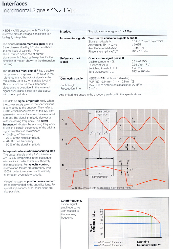
Below are scans from Heidenhain a showing a test device just for checking alignment and output of Heidenhain scales. Two questions

1. Does the Heidenhain test device PWM 9 offer any advantages over 'O' scope testing other than convienience factors (small size, same 12 pin connector, portable, etc) ?

2. Can you tell me, now that you know what reader head connector wire does what, exactly how to attach to a typical 'O' scope and what to be on the lookout for as I move the reader head across the scale ?

encodertest.jpg
 
I thought those were not square wave scales? Sine wave with an incandescent bulb??

Can do it with an oscope. A DSO would make it lots easier.

To find the pinout, find the + and the - There should be 4 other outputs that vary as you move the reader. Two will be opposite signals and that pair it either A & /A or B & /B . It really doesn't matter which is which because both pairs will act the same. There will be a phase shift between the pairs.
 
Yes....

Their tester appears to check all the relevant aspects of the output signal, and should allow you to get the light and whatevers adjusted to get signals centered in their acceptable ranges.

It apparently does NOT monitor the lot at once...

And there is an ominous note about "different expansion modules available for checking the different encoder signals". Sounds like what you see is the reader head, and you need several other goodies at extra expense to see all the relevant signals.

With the scope, you will be trying to check the various things individually. It looks like you want a 4 channel to see it all, but may be able to use a 2 channel to check one signal at a time.

The critical issue seems to be consistent timing between the two 90 deg square waves, and that requires seeing them both, so for final adjustment you would have to look at only one half of each differential signal with the 2 ch scope. Probably OK, maybe not.

You mentioned a problem that boils down to a speed problem. power feed ok, hand feed sends it into the weeds.

That suggests a problem that affects the signal amplitude from the analog reader head to the digital processing, so that a little faster feed, and it might not get the signal due to some sort of roll-off with frequency. Faster feed movement gives a shorter signal, meaning higher frequency. There is a comment about that in the spec.

The good thing is that you KNOW you want one thing, bulb adjustment.

I would think that you need to get the adjustments so that the square wave looks the same on both signals when in max speed power feed. Then seeing that each is centered up with its low-high or high-low transition at middle of the other pulse should do the job.

Amplitude AND duration of each high and low the same AND same as the other signal. Amplitude on the digital side is likely no problem. Duration of the digital pulse is likely affected by amplitude on the analog side of the head.

Then getting the two lined up..... Could be better done in reverse order (timing first, then amplitude), but I don't know... my suspicion is that amplitude will affect timing, so to do that first. They may be linked enough that you will end up needing to zero in both together.

Bulb position would definitely have an effect on the signal amplitude, I'd think.

There PROBABLY are test points in teh pickup circuitry.... that would allow you to see the analog side of the signal and adjust better to maximize the signal and adjust the relation between teh A and B sides, etc, etc.

At the end of the cable you are stuck with seeing the signal as processed.

That processing probably includes what is likely a "schmitt trigger" comparator, set to "decide" it has a signal at a particular amplitude. The bulb position etc would affect the point at which it decides it has a signal, by affecting the analog signal amplitude vs position.

You should be able to do it with the scope, but it may be rather insensitive to the adjustments, or seriously non-linear. And if you don't have the filament in the right spot, the other adjustments may be sorta meaningless...

Plus, at higher traverse speeds, the timing might get short. The mention of 0.25 uS (250 ns) timings suggests the need for a 'scope with over 100 mHz response.

As to how to set the screws.... no idea, and no guesses without seeing it.

But, from your statements about where the screws are it may be that they are intended to block light and set the edge of the light as it hits the scale. That, and the filament position, would change the edge of the light for each half of the scale, and thus the timing between them as the head moves (I assume it has a scale portion for each of the two signals).

Just my guesses, fwiw
 
All very useful stuff here. I want a PWM9 for christmas!
Is this related to the bulb replacement saga on an LS803? I thought that they were sine wave output (11uApp)?

Regards

Charles
 
Regard sine wave output, I think you guys are right about that. My spec scans were from the latest Heidenhain literature where most scales are square wave, but after posting it occured to me to look in an older catalog. Curiously, the LS 803 is not in the 1989 catalog (even though mine are of that vintage), but most, if not all of the scales back then were sine wave, so I assume now that this one was too.

Anyhoo, below are catalog scans from the ~sinusoidal~ wave spec sheets...sorry about the wrong assumption on my part


(I'm deleting the square wave scans from previous posts to save thread download time)

J, I like your theory on the purpose of the lens screws as that makes much more sense than using them to actually move the lens around.

encodertest3.jpg


encodertest4.jpg
 
Charles, current model Heidenhain sine wave scales give signal as "1 Vpp" whereas the LS 803 says "15 - 35 µAss"

Will a 1 Vpp scale work with a DRO that is used to receiving 15 - 35 µAss ? In other words, are these compatable ?
 
So that means (cringe) that Heidenhain no longer makes ~any~ scale that will replace an LS 803 ?

You will kindly note that A and V are spelled.
Uh, come again ? :confused:
 
One is voltage-output, and the other is current-output... the current-output will be probably expecting to drive into a mid-range impedance, and the voltage-output will be expecting to drive into a high-impedance. Consequently, the result of connecting one to the other will be a distorted signal (that probably won't be readable by the DRO head), or a blown driver chip. Matching the impedance, given the precision nature of the equipment, that it's analog, and the fact that it depends on interpolation, is probably not something you want to tackle... verifying it's accuracy will probably cost more than it's worth...

And yeah - of course, they don't make a replacement part that's compatible. Now you gotta buy a whole new DRO - see how this works? :rolleyes:
 
As far as I know there are 3 Heidenhain output formats. 1Vpp, 11uA and TTL. TTL has taken over now and is the standard.
Heidenhain sell converters ("interpolators" in their language) to change one to another. They also give circuit drafts for you to design your own if you're that clever - which I'm not.

When I've emailed Heidenhain in the UK for advice I've always got good service and a quick answer despite being an amateur. I think that the 15-35uAss question needs their input 'cos it's beyond me.

Regards

Charles
 
Don, can you keep a straight face when asking about "15 - 35 µAss"? ;) I've never heard of micro-butts before and would think that you're really looking at uApp (micro-amp, peak to peak). I think hammerhead has it nailed as far as what these units really mean (voltage output vs current output).

--Larry
 
If you want a quick and dirty way of observing the 35uA signal, put a 1k ohm resistor across it. This will result in (35uA x 1,000) = 35 millivoltss (for consistency ;)

Typically, the current output would go into whats called a transimpedance amplifier (an opamp with feedback to the (-) input and the current applied to that same input). A transimpedance amp with 1k ohm feedback would give the same 35 millivolts out as the 1k resistor but better behaved (bandwith, impedance and other goodies).

I would think that a 1 volt output scale could satisfy a 35uA input system with a pretty simple circuit. If their input circuit is a good transimpedance setup, it will have near zero ohms input as it is a current to volt converter.

That being the case, 1 volt, applied thru a 30k ohm resistor would give 30uA to the Heidenhain. If their signal is balanced, differential (which it appears to be), split the 30k into 15k and 15k per signal. The resistors may need some small compensation capacitors across them if response it too slow on fast motion (not likely if you're turning a crank ;) )

For quick and dirty, buy whatever Heidenhain has for converter. Doesn't Sony have current output scales (or maybe they were millivolt output)??

Den
 
Digitizing scopes are pretty cheap these days and should handle this problem pretty effectively. A standard analog scope would be difficult to use unless you can get the output to be periodic enough to get reasonable triggering.

I have a scope from bitscope (no affiliation) and it is quite nice - hooks up to your PC and runs over USB. There are other folks doing similar things.

Bitscope DSOs

Cheers,
Bob Welland
 
Don, can you keep a straight face when asking about "15 - 35 µAss"?
I copied and pasted that direct from the link that Charles Ping supplied above...apparently the Germans do have microbutts !


I just now got the LS 803 adjusted to perfection and didn't need no stinkin scope !

So now I'm less inspired to go mucking about with the O scope, but it is interesting to get the info on how to "do it" and I'll sure keep my eyes peeled for a used Heidenhain PWM 9 tester. In looking thru older literature I see there were earlier generations of that tester as well, one designated PWM 7, with analog needle rather than LCD display, so perhaps one of those will pop up on eBay someday. (except now Ping will be running the bids up !
)
 
Don, What do you think the annual market would be for a small box like that with interfaces to the top 3 or 4 interface types? What do you think a fair sell price might be? Den
 
Might be that its easier to adjust this..... due to it being analog. (Probably easy to get way off also, although that's possible either way)

But, if both signals are maximized, and also set to correct phase, you should get good reads.

Since you know that the bulb is the issue, that means everything but position and those silly screws are correct, all you need are good signals, and presumably all you need to mess with are the bulb and screws. Likely, the bulb, if in correct place, would get you nearly or completely there.
 
Don:
Here are the pin outs for the LS 803:
PIN#
3 + 5v +- 5% apprx. 120 mA lamp filiment
4 - 5v +- 5%

1 + Measuring Signal 0* 15 - 35 uApp
2 - Measuring signal 0* 15-35 uApp

5 + Measuring Signal 90* 15-35 uApp
6 - Measuring Signal 90* 15-35 uApp

7 + reference pulse 4-15 uA
8 - Reference Pulse 4-15 uA

9 Open not used.....

According to the reference sheet recieved with a new LS 803 scale the output of the reader head is:

Two sinusoidal signals, phase shifted by 90*
Output current: 15-35 uA at 1 Kilohm (incrimental track signals)
4 to 15 uA at 1 Kilohm (reference signals)

Cheers Ross
 
J, I fixed it tonight...works perfectly now..no errors no matter what.

It was helpful for me to see an illustration of exactly how it works...that way I had a better idea of how the light had to align with the lens. Would probably have been easy with a microscope but I didn't want to disconnect the cable from the machine so had to eyeball it and keep trying...maybe I just got lucky.

Can post that illustration if anyone interested.

www.practicalmachinist.com/ubb/ultimatebb.php?ubb=get_topic;f=1;t=015400

Don, What do you think the annual market would be for a small box like that with interfaces to the top 3 or 4 interface types? What do you think a fair sell price might be? Den
Dunno Den...this is kinda new for me too, so haven't given that much thought. Seems like a Heindenhain rep or distributor might be willing to give you that answer, but don't depend on just one...ask many of them as you might get different answers.

I do know that Heidenhain needs someone to design and manufacture an interface for their top of the line DRO, the Positip 880. It has some functions applicable to controlling relays on automated systems, but the interface box needed to actually "do it" is still not available due to some design flaws in the first prototypes, which I have the impression are being sourced out.

(I only know about the Positip situation because I was looking at possibly using one to replace the TNC 113 "active" DRO I was having trouble with, and with that interface box that doesn't yet exist, I could have made that DRO "active" as well. Plus it would have been all new, cool color LCD screen and such. Where it all falls apart is that it would have cost $2,500+ by the time the dust settled :eek: )


Back
Top