cinematechnic
Cast Iron
- Joined
- Apr 11, 2005
- Location
- Walnut Creek, CA
I’m about to make my third toolpost hold-down bolt for my Hardinge HLV-H in less than a year. This new one is going to be for a Multifix E toolpost.
I haven’t had any problems with the bolts I’ve made but I wanted to tap into the vast knowledge base here. Just want to know if I’m doing things the right way and if anyone has any suggestions.
I tried advanced search and literally got nothing. Perhaps it a description problem with people using different terms to describe “hold down bolt”.
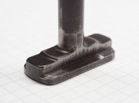
Please see the attached photo.
On the left is the T-nut I got with the KDK Series 100 toolpost, likely made by the shop that previously owned the HLV-H. It appears to be stainless, and hase a 7/16 - 14 thread. It is partially threaded so the bolt cannot go through the nut and contact the bottom of the T-slot.
In the middle is the bolt I made for my KDK Series 0 toolpost. It is made from C1215 steel and has a flat head (countersunk) 3/8-16 bolt that inserts from below. The pressure of the bolt being pulled upwards into the “T” part keeps it from rotating.
On the right is the bolt I made for my Tripan 111 toolpost, again made from a bar of C1215. Tripan are small and very precise toolposts commonly used on Schaublin lathes (my other lathe is a Schaublin 102N). The design is similar to the bolt for the KDK 0 but uses a M10 x 1.5 bolt and has a cylindrical projection to fit into the bore at the bottom of the Tripan and locates the 5/16” riser plate that compensates for the difference in center height between the HLV-H and the Schaublin so that I can swap toolholders between the two machines.
The bolt for the Tripan fits tighter and does not rotate at all even with no pressure being applied. I think it might be because of the longer unthreaded section fitting tightly against the bore I made in the “T bushing”.
What’s different this time: The Multifix E is about the biggest toolpost you’d want to put on a HLV-H. At it’s core is a hardened and ground splined cylinder 75mm in diameter. It can accept a bolt of up to 20mm and has holes for two 6mm pins that can be put into the T-nut to prevent the splined cylinder from rotating on the compound.
I don’t take heavy cuts and I’m usually operating on the “low” speed (0.5 HP), but I like the idea of having the Multifx setup being very rigid as this helps when you need very high accuracy (better than .001”) which I frequently do.
My questions are:
1. Is a bolt coming from below with a nut on top of the toolpost superior for any reason other than eliminating the possibility of the bolt driving through the T-nut to the compound? The stainless T-nut I'm using on the HLV-H (left side of photo) has an incomplete thread to prevent this
2. Is there any relationship between toolpost size and the size of the T-nut where it contacts the T-slot in the compound? In other words, how big should the contact are of the T-nut be to distribute the clamping force evenly and be sufficient for the size of the toolpost?
3. Any comments on materials? Is unhardened C1018 type steel OK? I used C1215 for the two previous ones but they were small enough that they could be made from 1.125” bar. Many more sizes and shapes availabel in C1018.
Thanks in advance!

I haven’t had any problems with the bolts I’ve made but I wanted to tap into the vast knowledge base here. Just want to know if I’m doing things the right way and if anyone has any suggestions.
I tried advanced search and literally got nothing. Perhaps it a description problem with people using different terms to describe “hold down bolt”.
Please see the attached photo.
On the left is the T-nut I got with the KDK Series 100 toolpost, likely made by the shop that previously owned the HLV-H. It appears to be stainless, and hase a 7/16 - 14 thread. It is partially threaded so the bolt cannot go through the nut and contact the bottom of the T-slot.
In the middle is the bolt I made for my KDK Series 0 toolpost. It is made from C1215 steel and has a flat head (countersunk) 3/8-16 bolt that inserts from below. The pressure of the bolt being pulled upwards into the “T” part keeps it from rotating.
On the right is the bolt I made for my Tripan 111 toolpost, again made from a bar of C1215. Tripan are small and very precise toolposts commonly used on Schaublin lathes (my other lathe is a Schaublin 102N). The design is similar to the bolt for the KDK 0 but uses a M10 x 1.5 bolt and has a cylindrical projection to fit into the bore at the bottom of the Tripan and locates the 5/16” riser plate that compensates for the difference in center height between the HLV-H and the Schaublin so that I can swap toolholders between the two machines.
The bolt for the Tripan fits tighter and does not rotate at all even with no pressure being applied. I think it might be because of the longer unthreaded section fitting tightly against the bore I made in the “T bushing”.
What’s different this time: The Multifix E is about the biggest toolpost you’d want to put on a HLV-H. At it’s core is a hardened and ground splined cylinder 75mm in diameter. It can accept a bolt of up to 20mm and has holes for two 6mm pins that can be put into the T-nut to prevent the splined cylinder from rotating on the compound.
I don’t take heavy cuts and I’m usually operating on the “low” speed (0.5 HP), but I like the idea of having the Multifx setup being very rigid as this helps when you need very high accuracy (better than .001”) which I frequently do.
My questions are:
1. Is a bolt coming from below with a nut on top of the toolpost superior for any reason other than eliminating the possibility of the bolt driving through the T-nut to the compound? The stainless T-nut I'm using on the HLV-H (left side of photo) has an incomplete thread to prevent this
2. Is there any relationship between toolpost size and the size of the T-nut where it contacts the T-slot in the compound? In other words, how big should the contact are of the T-nut be to distribute the clamping force evenly and be sufficient for the size of the toolpost?
3. Any comments on materials? Is unhardened C1018 type steel OK? I used C1215 for the two previous ones but they were small enough that they could be made from 1.125” bar. Many more sizes and shapes availabel in C1018.
Thanks in advance!