What's new
What's new

Bodine DC Gear drive wire question

challenger

Stainless
Joined
Mar 6, 2003
Location
Hampstead, NC-S.E. Coast
I am about ready to start building my honey extractor and will, hopefully, use an old Bodine right angle gear motor. It is 1/8hp and the tag says 115vdc but I've been told that the controller I have which is a kb industries unit-w-a 90vdc output will work fine.
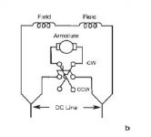
My question is about the four leads that come out of the motor. There are 2 black and 2 blue leads. For the heck of it I measured the resistance on each. There is no continuity between the blue wires and the black wires but there is 10 ohm between the 2 blue wires an 742K ohm between the black wires. I've looked all over the Bodine site and cannot find anything. I called and they said it was no longer supported. If anyone can give me tip on the use of these 4 wires I'd greatly appreciate it.
Thanks - Howard
 
Measure again, this time slowly spinning the motor armature, if you can do that somehow.

The open connection would probably be the armature, and is due to probable low voltage from the ohmmeter. Could be that it really is open, but........... brushes can measure open at low voltage as from digital meter.

If you have a cheap meter with a real analog dial (pointer type) use that.
 
Bodine makes several different kinds of motor. The DC ones with four wires are usually shunt wound, and the motor model number will have "SH" in it. Series wound motors ("SE") can have four wires if they are meant to be wired to an external reversing switch. But series motors will run on either AC or DC, so you probably have a shunt motor.

Before you put power to the motor, you need to know what kind you have, and that your controller is for that kind of motor. Four wire motors can be either shunt or series and there is no internal connection between the two sets of wires.

Larry
 
The 10ohm reading is most likely the armature, to try a test to see if it is permanent magnet field, leave the high resistance conductors open and measure the voltage across the 10 ohm ones while rotating the armature by back feeding with another motor etc, the voltage output will be proportional to rpm if permanent magnet.
You may get a small amount due to residual if wound field, but it should climb drastically with rpm if P.M..
At the rated rpm it should put out ~115vdc.
Minder.
 
Last edited:
OK-so I am to go across the 2 blue leads-w-a meter while leaving the 2 black isolated and when rotating the motor the meter will read a climbing voltage. I will do this however if this proves out the case that it is a PM motor what does this show me about the 2 black leads? I suspect the 2 blue armature leads are not polarity sensative and will just rotate the motor in one direction or the other yes?
Thanks-Howard
 
It would if it was a series wound motor and not a shunt wound
A series wound motor has a low-resistance field winding.
A shunt wound motor has a high-resistance field winding.
My advise would be to pop the end bell off and have a look see. It should be fairly easy to see which colors go to the brushes.
 
If it is a PM motor, it can only be a shunt motor.
If the motor armature, the output of the two low resistance leads will change polarity with direction. Or conversely, change direction of the motor if fed with reversing DC.
If it looks like it is a PM motor, input a supply such as a automotive battery and with the high resistance leads open, see if the motor exhibits torque, if wound field it will be easily stopped.
Minder.
 
Its quite possible, especially if it is a very old motor, I was just pointing out a method to determine if it was PM without maybe dismantling.
IF PM then it does leave the question of the other 2, generally on a PM motor, anything apart from the armature is tach or temperature sensor.
If temp sensor, it would have to be the Thermister type, not thermal on/off switch.
Minder
 
If it is a PM motor then it should have a magnetic pull of some sort, all of the time. Perhaps checking this with a piece of steel ( screwdriver...maybe) against the stator? It will also have much more resistance to spinning by hand and will stop spinning faster...but if it is a gear motor this would be inconvenient to check.
 
Sheesh...... 2 days of yak-yak for a simple 2 minute measurement........

Spin the armature (rotor) and measure the "open" wires.

They will vary in resistance or not.

if they do, and it is an "off-on" once or several times per rev, from zero to open, it may be a tach.

if they do, a bit, but hover in one general area, it probably has brishes, and further investigation is needed to determine what it is exactly, but it probably is shunt.

if they do NOT vary in resistance, either the motor is shot, or the wires are for some other purpose, possibly a thermal sensor etc.

if a sensor, it shout be readable on a higher scale if it is a thermister. A real normally open thermal switch may be for a shunt-trip breaker or whatever. less likely, but possible.

if any part of the motor appears magnetic, it could be PM. If you see windings on the non-moving part, it is not PM.

Having only two wires does NOT make it PM, it means it still could be internally connected series, or shunt, compound, whatever.

So what did you find?
 
2 days???? Hey, I can't help I am a slow typer...typist...typographer...whatever. Time flys but I honestly didn't realize I was typing for two solid days. I gotta get some sleep...EOM!
 
Or the owner of the motor could simply give all (not just 1/8HP, 115VDC) of the nameplate data. As you say, a lot of time wasted on this.

Larry
 
Maybe so ...but is there any reason to be rude about it? Or.....If you don't like or are uninterested in the thread....don't read it. And definitely don't reply...But I find that this egotistical/rude/impatient attitude is quite prevalent on internet "discussion" forums. But I don't run into it much in public. Maybe the "smart" guys on here can tell me why? Or would it be a "waste" of their time?
 
Sorry to be a burden. If anyone would like to tell me to take this motor and shove it I can accept that.
I tried posting a picture yesterday along-w-a rather detailed reply. From all indications the post went through but in looking today this post didn't make it to this thread. Hopefulluy it will appear now.
The photo isn't very clear due to the size constraints but it is a model NSH-54RL. As I mentioned earlier it is a 1/8th hp and after reading some of the appreciated replies I would say it is a shunt wound motor. I don't have a very good understanding of the types of DC motors so I greatly appreciate the good advice. As anyone reading this thread can tell I am unsure of the role of 4-wires. I now would say, given the replies to my posts that it is a PM motor and the 2 black wires are for ???. I will take the motor apart enough to see where the leads go.
As for my questions becoming so unbearably tiresome I apologize profusely and I mean that from the heart of my bottom.
Thanks for the help to those that willingly read and reply-w-the much needed advice. You obviously saw the thread and chose to participate in helping me. I applaud you for making the choice to do so. After all it this thread was never forced on to anyone's screen like a pop-up was it? I hope it wasn't! If it was then please inform the proper authority having jurisdiction.
Howard
Hampstead, NC
 

Attachments

  • Bodine-KBIC.jpg
    Bodine-KBIC.jpg
    61.9 KB · Views: 1,776
Last edited:
Howard The picture is barely readable, but just by looking at the bell housing style it does appear to be one of the older Bodine wound field motors.
Maybe you can just post the information off the plate maybe it will shed more light.
One thing is pretty much for sure, if it is a wound field, it will be shunt connected with those readings.
Did you try the voltage test?
Minder.


Back
Top