What's new
What's new

Lathe problems

Klaus

Cast Iron
Joined
Jan 9, 2005
Location
El Paso
Hello!

I recently bought a new lathe and put in to my gararge.
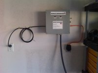
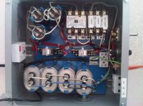
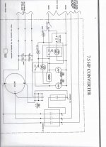
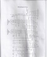
I installed a rotary 3-phase converter and hooked up the lathe.
So far so good.
When I connect the 120V plug for the control panel of the RFC the power and ready light is coming on.
I push the power button and the the RPC starts turning.
Motor of the lathe is 3HP and RPC is 7.5HP.
So far so good.
When I turn on the lathe the motor flinches and don't turn.
The RPC makes a strange noise.
The motor of the cooling pump is working.
Jogging don't work either, just flinches and that's it.
Attached some pictures of the lathe and hook-up.
Need help urgent!!!

Klaus
 
Photos

Please check out the pictures and try to help me please what I did wrong!:bawling:

Klaus
 

Attachments

  • 3 phasen converter steuerbox.jpg
    3 phasen converter steuerbox.jpg
    69.5 KB · Views: 324
  • lathe 175.jpg
    lathe 175.jpg
    91.7 KB · Views: 326
  • lathe 176.jpg
    lathe 176.jpg
    89.4 KB · Views: 314
  • lathe 177.jpg
    lathe 177.jpg
    82.8 KB · Views: 302
  • lathe 178.jpg
    lathe 178.jpg
    90.9 KB · Views: 252
You forgot to mention whether you have 220 or 240 V single phase going to the RPC and whether your motor is wired for 220 or 240 V three phase. And is there a magnetic starter on the lathe? If so, you have to be aware of how to run the three phase from the RPC to the lathe input connections. A magnetic starter coil has to be connected to the same two wires that come from your single phase supply. The phony third phase from the RPC will run a motor, but it won't work on a starter coil or on a control transformer. And of course you can't run a 440 V motor from a 240 V RPC.

Larry
 
Lathe problem

Hello Vince.

I have 120V to run the control box.
I mesured 248V single phase coming in to the box.
The motor supposed to be prewired for 220V.
I have no clue about the stater coil.
There is a connection box in the back with 4 connectors.
I assume it's going to be for 3 phase and ground?

Klaus
 
It appears that he has the motor connected for 240, but the control unit is plugged into 120. The first question is whether there is another 240 single phase line coming in.

Bill

Edit. Or is that the phase converter motor in the wire hookup pictures?
 
Cable

Hello!

As you can see on the second picture, there is a 120V cable coming in to the 120V connector.
That's for running the controls.
From the right there is a orange cable coming in from 220V and goes to the 220V hook-up on top of the 2 phase.

Klaus
 
Klaus and I were writing at the same time. If there are 4 terminals on the lathe, 3 would be the power and the other would be ground or the center of a y connection, unlikely. Normally ground wires are green in this country, but if the unit is European, it could be different. Getting them mixed up could be serious, or fatal if the lathe doesn't have another ground connection. It sounds like you need someone familiar with electrical circuits on the scene.

Bill
 
If a nine wire motor connected for 240V, #5 has to be hooked to 4 and 6 but nothing else.

Feed #1 and #7 together with one hot of 240 single phase
Feed #3 and #9 together with the other hot of 240 single phase

Shoot three phase out to load with:

#1 and #7 together
#2 and #8 together
#3 and #9 together

Run caps usually are in between #1 and #7 and #2 and #8
Some have additional run caps between #3 and #9 and #2 and #8


John Oder
 
Hello!

@9100: my ground wire is blank
@johnder: I have no clue what you are talking about

I only hooked up the orange cable, the rest of the RPC came like it is.(Picture 2)

red wire is connected to U2-4
white wire is connected to W2-6
black is connected to V2-5
blank to the ground in the RPC

Klaus
 
Lathe problem

Hello!

Here is apicture from hook-up in the rear of my lathe!

Klaus
 

Attachments

  • lathe 180.jpg
    lathe 180.jpg
    81.6 KB · Views: 222
Can you post the diagram for the RPC? It looks kind of odd the way it appears to be wired in the pic.


..and the diagram for the lathe!
 
Lathe problem

Hello!

Here are the diagrams as an attachment.

Klaus
 

Attachments

  • RPC.jpg
    RPC.jpg
    85.9 KB · Views: 181
  • Lathe.jpg
    Lathe.jpg
    76.1 KB · Views: 221
first it looks like the box is not wired correctly.Maybe take a deep breath
and do some reading until you understand how a phase converter works.
If you feel that you must continue blindly ,do you have a volt meter?
Check and see if you have power coming out to the motor.Check across each phase, not to ground.No power motor will not go.The voltage also has to be 220 volts but it will read slightly higher.
 
Here is an observation - correct me if I am wrong.

The photo showing the RPC idler motor terminal box:

I can see the the three taped connections sort of sticking straight up that the bluish, whitish and blackish wires coming from the control box go to. This should make the RPC idler motor go.

You can look on the black disc all these wires come out of this motor thru and see what the numbers are - no letters.

The great big problem is is that you have the orange cable (red, black white and bare ground) going to lathe is connected to motor wires 4, 5 and 6 (humor me and ignore the letters for now - just look at the black disc to confirm what I just wrote.)

This won't work.

The red, black and white going to the lathe need to be in those three "sticking up" taped connections, and the 4, 5 and 6 need to be connected together, taped, and connected to nothing else.

John Oder
 
Lathe problem

Hello I just measured the voltage between the following wires, that are going out from the RPC to the lathe

Red- white 326V
Red - black 256V
black white 110V

@johnoder
You mean I have to connect my orange cable with the blue/white/blck cable that comes out on picture 3?

Klaus
 
Yes - photo 176 is what I was writing about. Untape the three bundles and connect in red, black and white (one in each bundle please:)) in those bundles and retape.

Tie 4, 5 and 6 together and tape - connected to nothing else. These will be the ones that you used to have the orange cable attached to.

Bet it helps.

If it runs backwards, try swapping two of the three at the easiest place to swap, like the lathe.

Be careful. This is ELECTRICITY.

John Oder
 
Klaus,

*** Edited out so as not to confuse with John's instructions - I had Klaus take his late out completely first to check legs, then put his lathe in the circuit.


What John says should work. - If not your wire groupings may not match what is on the RPC motor data plate.

Also you should replace the solid core wire with stranded wire.
 
Last edited:
Lathe problem

Hello Johnoder!

YOU are the men!!!!!!!!:bowdown:
It's alive!!!!!!!!!!!!!:Ithankyou:

But just out of curiosity, what are the other cables are good for?

Klaus
 
That posted diagram that might be the wiring for the lathe seems to show a two-speed motor, a control transformer and numerous relays (magnetic starters). That is not a simple thing to hook up to a RPC unless you really understand what you are doing. I suspect the average home builder type licensed electrician would still not have a clue about RPC's and lathes.

And yes, the 220 wall plug should have stranded wire, like 6-3 SJO or some such, to feed the RPC. An electric range cord set might work, if rated for the same current as the RPC.

Larry


Back
Top