What's new
What's new

Capacity of 3/4" plate

gmach10

Hot Rolled
Joined
Dec 27, 2008
Location
N.E. Illinois
Hello all its been a while. Here's what I got. I have to lift the armature of a vertical electric motor. Total weight is supposed to be 3200 lbs. The thrust bearing is bad (located on the top). Any ideas of removing the whole motor is out. Here's the catch, the only way is to push up is from the bottom. This motor powers a pump about 4 stories bellow via a driveshaft. With the shim pack of the coupler removed I only have 7/8" of gap between the faces of the couplers. So, would a piece of 3/4" x 6" with two holes drilled and tapped for 5/8" bolts at each end for jacking purposes approximately 22" wide handle the 3200 lbs.? I need to do this because there's a hole that has to be spanned that's 19" in diameter. I hope my description makes sense.
As always any help would be appreciated. Thanks Glenn
 
There is a section in older machinist handbooks that talks about something similar to what your asking.

Personally, just change the motor, less down time, unless you've really got a screwed up tight clearance area with absolutely no way to get it out...

If the thrust bearing is bad there is also a good chance the lower bearing is worn as well...

Most of the time a vertical pump motor is either a solid shaft or hollow shaft.

Solid shaft motor couplings are usually a spacer coupling with two boss fits and around 4"- 6" of clearance...between shafts.....
 
As I said removing is not option. The lower bearing has the ability to move up and down within it's bore. I just need to support the weight to remove and inspect the upper thrust bearing. Tried removing the coupler from the shaft with little success. This motor is one of three, naturally the furthest from the door. There is an overheard crane but through some engineers infinite wisdom they didn't bother to measure the needed head room. The engineers who put his building on line in the late 1930's realized that at some point in time things need to be fixed and their design for the original motors worked. Todays engineer with the replacement motors not so much. So back to my original question how can I calculate if the plate can handle the weight?
 
There's a whole chapter in Machinery's Handbook on calculating stresses in various shapes. It is going to take a fairly long reading session to figure it out. I leave that to you. But I believe the answer is there.

You are going to have to know the alloy and any heat treatment it may have had.

I would think that a piece of six inch or even larger channel would be a better choice.

I would suggest that you use four bolts for jacking it up instead of two. If you try to balance the load across 20 inches, keeping the shaft exactly centered between the two bolts, you are almost certain to have it flip on you. And then you will have removed the motor or at least the rotor in it. I would put two bolts on each end, one about 1" from each edge. That way it can't flip.

I guess I wasn't clear, but there is two holes on each end for stability. Our selection of material is extremely limited. Also the OD of the coupler is 11". My thought was to put a bolt with a point that could locate the drilled center to help hold everything in a vertical position but the coupler is mounted 7/8" beyond the end of the shaft. "We the willing led by the unqualified have been doing so much for so long with so little are now qualified to do absolutely anything with positively nothing". Sometimes I think we could teach McGiver a thing or two!
 
Do you have a PDF or print of the motor?

Why does it have to span 19" if the coupling doesn't want to move and it's 11" OD?

How thick is the coupling?

An Overhead "I" beam crane?

Do you have pictures?
 
My calculator says 5200# stress at the center of 6 x .75 plate supported by 5/8 rods on 22" centers. Don't drill the plate for a center bolt to support the end of the shaft. Instead tack weld a stub shaft or even a piece of pipe to the plate to support bottom end of shaft. Double nut rods to prevent sideways tipping. You will need to heat new bearing to 250F and quickly slip it onto shaft all the way to the shoulder. And now the disclaimer. THIS ADVICE IS WORTH WHAT YOU PAID FOR IT. USE IT AT YOUR OWN RISK.
 
Do you have a PDF or print of the motor?

Why does it have to span 19" if the coupling doesn't want to move and it's 11" OD?

How thick is the coupling?

An Overhead "I" beam crane?

Do you have pictures?

Sorry no pics. There is a "I" beam BUT the what we refer to here in the Midwest as the pecker head (the facility on the motor to except incoming leads) is a 3'x3' metal box that sits directly above everything. BTW as stated earlier this is the last in a row of three motors. To remove this one motor completely the pecker heads would have to be removed on the other two to provide the overhead clearance. The physical size of each motor is about 5' square and equally as high. The 19" span is because of a hole directly bellow the motor where it couples to the drive shaft. With rainy season near the people of the area would probably not appreciate us taking this pump station down.
My son is going to school to become a civil engineer, we're going to have a very serious conversation about designing things with maintenance in mind.
 
My calculator says 5200# stress at the center of 6 x .75 plate supported by 5/8 rods on 22" centers. Don't drill the plate for a center bolt to support the end of the shaft. Instead tack weld a stub shaft or even a piece of pipe to the plate to support bottom end of shaft. Double nut rods to prevent sideways tipping. You will need to heat new bearing to 250F and quickly slip it onto shaft all the way to the shoulder. And now the disclaimer. THIS ADVICE IS WORTH WHAT YOU PAID FOR IT. USE IT AT YOUR OWN RISK.
Thanks deltap. I'll let everyone know the outcome. Probably wont be back out there for a while. We we're able to dry run our prototype and it wouldn't fit. Original plate was 1" thick. We thought, loosen motor coupler slide it up on the motor shaft till was flush with end of shaft, slide our plate in, put an indicator on the armature, put a little upward pressure see if it moves. I'll get the name of the coupler they used to see if anyone has had experience with these. I think it was made in Germany. 4 pieces, the hub one ring with 12 threaded holes, a sleeve with a taper at each end and another ring with holes that permit bolts to go through into the threaded holes of the lower ring. Tapered sleeve slides over the hub, rings when tightened together against the tapered sleeve apply "squeeze" to hub locking it to the shaft. Seems much more complicated a design for what it has to do in the place its installed.
The goal is to raise the armature (as little as possible) to get the weight off the thrust bearing so it can be removed for inspection. There is an inspection plate on the top of the motor to allow for removal of the bearing.
 
Unfortunately, I do have experience with shrink couplings and shrink disk.

Example: Home

pictures : Products

The fun doesn't start until you get one for very large shafts and have helpers who pull through the click of a torque wrench..

Then after that's maxed you move to a hydraulic torque unit.

.. It takes several hours just to draw up a large shrink coupling following a sound procedure..
 
Is there any reason that 2 flat bars couldn't be used to give more stability as a platform? Then you could use thicker material if you like, and have a semicircular depression machined out of the center of each bar (making it 3/4" thick there) to accommodate the 11" hub OD. Slide them in from each side and then proceed to jack with setscrews.
 
Worth adding in these kinda situations, hardox, weldox or similar high tensile steels can give you a good 2-3x the strength of regular mild steel yet still bend - not snap violently if over loaded.

If you have a press with a pressure gauge stuff like this is really easy to prof load well enough to at least have a yay - nay and some idea of spare capacity.
 
Not sure I understand this. The vertical motor drives a 4 story-long shaft that runs a pump. There is a coupling on the bottom of the motor, with some shim between it and the long transmission shaft. The transmission shaft goes through a 19" hole below the motor. The motor has at least two bearings. The bottom one is radial service only, and slides up and down in a sleeve. The top has at least one bearing, a thrust bearing. This bearing supports the armature weight. Its purely a thrust bearing, so we will assume that there's another sliding radial bearing at the top of the armature shaft. There is no clearance for a crane on top, and other factors (such as the electrical service box placement) make any process of creating clearance impractical. You want to disconnect the bottom coupling from the long transmission shaft, and loosen the coupling and slide it up the shaft, leaving a space between the end of the armature and the long transmission shaft. You wish to use that space to put in a "beam" made of 3/4 steel, 6 inches wide by 22 inches long. Using the surface where the 19" hole is as a support, you wish to jack the "beam" up, which you hope will lift the 3200lb armature. As I understand it, you wish to lift it enough so that you can inspect the thrust bearings that usually support the armature. If they are knackered (as you suspect that they are), you'll need to remove a coupling from the top (while supporting the armature from below), and will replace the thrust bearings (and perhaps the radial ones? - I'd think you only one to pull this stunt once in your lifetime). Then you replace the top coupling, lower the armature, test it to ensure it runs properly, and then you can loosen the lower coupling, slide it down to mate with the long transmission shaft, and then make secure the couple.

Yes?

My only suggestion would be to make the plate wider if you can. Makes it heavier and less easy to sling around, but an 8 inch or 10 inch wide plate will flex less.

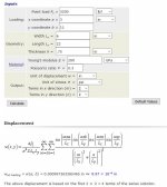
That said, this efunda page gave me a displacement of about 0.001 inch under your load condition. I may have done it wrong, however - the drawing is not clear I think. Page is here: http://www.efunda.com/formulae/solid_mechanics/plates/calculators/SSSS_PPoint.cfm#Results

Inputs I used are below.

plate.JPG
 
Why do you think the lower bearing is still good? Before proceeding I would inspect the lower bearing real carefully. maybe a come along and a DTI to check for radial slop. I would think if the top bearing is worn all the bearings are near the end of their life. be a shame to go to all that work only to have to pull the motor in a year to replace then lower. How about the bearings down at the pump you will probably have to pull the motor to replace those as well.
Of course you may be retired by the time the other bearings need replacing . How old are you? within a few years of retiring?
Bill D
 
I might have worked on a motor built like this recently (rotor and endbell brought to my shop). The top thrust bearing was a single angular contact. There was room in the housing and on the rotor for two of these bearings back to back, but I guess, in the real world, the one bearing never ever took any load, so they just left it out and put spacers in. I think the bottom bearing was a straight roller, and it had a pretty easy life.
 
OK, I guess I was imagining a coupler in the range of 1" to 2". That 11" diameter, if it provides support all around it's periphery, should provide good stability. But it changes the calculation as the load will not be at a single point, but at two points, each 5.5" from the center. Again, this is one of the cases outlined in Machinery's Handbook. And it actually makes the situation better.

Gut feeling: if we are talking about steel plate, it will work just fine. In any case, trying it should be safe. After inserting the plate that thrust bearing will still be holding the weight, won't it? So you jack it up a quarter or a half inch with the screws and then give it a few hard, downward pushes. Then back it down and check the plate. If the plate does not bend past the elastic limit, then go ahead. Perhaps add a safety chain on each side for extra confidence. Be sure each chain can handle the full load/weight.


I guess I wasn't clear, but there is two holes on each end for stability. Our selection of material is extremely limited. Also the OD of the coupler is 11". My thought was to put a bolt with a point that could locate the drilled center to help hold everything in a vertical position but the coupler is mounted 7/8" beyond the end of the shaft. "We the willing led by the unqualified have been doing so much for so long with so little are now qualified to do absolutely anything with positively nothing". Sometimes I think we could teach McGiver a thing or two!
 
Not sure I understand this. The vertical motor drives a 4 story-long shaft that runs a pump. There is a coupling on the bottom of the motor, with some shim between it and the long transmission shaft. The transmission shaft goes through a 19" hole below the motor. The motor has at least two bearings. The bottom one is radial service only, and slides up and down in a sleeve. The top has at least one bearing, a thrust bearing. This bearing supports the armature weight. Its purely a thrust bearing, so we will assume that there's another sliding radial bearing at the top of the armature shaft. There is no clearance for a crane on top, and other factors (such as the electrical service box placement) make any process of creating clearance impractical. You want to disconnect the bottom coupling from the long transmission shaft, and loosen the coupling and slide it up the shaft, leaving a space between the end of the armature and the long transmission shaft. You wish to use that space to put in a "beam" made of 3/4 steel, 6 inches wide by 22 inches long. Using the surface where the 19" hole is as a support, you wish to jack the "beam" up, which you hope will lift the 3200lb armature. As I understand it, you wish to lift it enough so that you can inspect the thrust bearings that usually support the armature. If they are knackered (as you suspect that they are), you'll need to remove a coupling from the top (while supporting the armature from below), and will replace the thrust bearings (and perhaps the radial ones? - I'd think you only one to pull this stunt once in your lifetime). Then you replace the top coupling, lower the armature, test it to ensure it runs properly, and then you can loosen the lower coupling, slide it down to mate with the long transmission shaft, and then make secure the couple.

Yes?

My only suggestion would be to make the plate wider if you can. Makes it heavier and less easy to sling around, but an 8 inch or 10 inch wide plate will flex less.

That said, this efunda page gave me a displacement of about 0.001 inch under your load condition. I may have done it wrong, however - the drawing is not clear I think. Page is here: http://www.efunda.com/formulae/solid_mechanics/plates/calculators/SSSS_PPoint.cfm#Results

Inputs I used are below.

View attachment 194671
There is no top coupling. Only an inspection cover to access the upper bearing which appears to be held on to the motor shaft with a Timken nut to allow for adjusting the end play. There is a procedure for adjusting the thrust clearance in the service manual. This is in an unmanned station so it might have been making noise for a few days. A stethoscope verified the noise and vibration coming from the upper bearing. That is why we split the coupler, to make sure the vibration wasn't coming from either the pump or one of flange bearings. The drive shaft attaches to the bottom only. The drive shaft passes through several flange bearing as it descends down to the pump. HuFlungDung nailed it, singular angular bearing. That's what it appears to be from the service manual provided. This is an inspectional operation. If its determined that the upper bearing in worn the plan is the replace it and keep this pump as a back up.


Back
Top