What's new
What's new

A cool little fabricating project

implmex

Diamond
Joined
Jun 23, 2002
Location
Vancouver BC Canada
Hi All:
I just ran a kind of neat little fabricating job; some tiny stainless steel tubes with side ports for a prototype medical device.
I thought I'd share a few pictures.

The angled holes were sinker EDM cut, the side tubes were coped on the wire EDM and the welding was done by YAG laser under the microscope.

3 kinds of high tech for a simple little job...I had fun today!
I love my toys!!:cloud9:

Cheers

Marcus
Implant Mechanix • Design & Innovation > HOME
www.vancouverwireedm.com
 

Attachments

  • DSCN4615.jpg
    DSCN4615.jpg
    90.5 KB · Views: 901
  • DSCN4618.jpg
    DSCN4618.jpg
    95.6 KB · Views: 917
  • DSCN4619.jpg
    DSCN4619.jpg
    96.4 KB · Views: 848
  • DSCN4620.jpg
    DSCN4620.jpg
    87.7 KB · Views: 866
  • DSCN4626.jpg
    DSCN4626.jpg
    96.7 KB · Views: 965
I didn't realize that accurate work like this could be done at such a small scale. Very interesting indeed.

But hey, you're behind the times using obsolete currency for scale. Get yourself a nickel and turn that penny in for more than the face value in scrap copper value. ;)
 
You're certainly a detail man Implmex. Always top-notch work.

I could weld that job into a blob LOL.

Looks like the penny was used as a cushion/conductor pad for a clamp jack screw on an EDM.

When you dream, is everything in miniature?

I think you have some rare talent.
 
Nice. I too am using now a laser welder for small jobs. In the past (and still occasionally now) I was using a plasma needle welder (Linde C-5) for this type of work. Another useful tool I use for small welds is a micro-TIG welder. Sometimes the assembly is too small or complex for welded fabrication. I found it is easier to make those by electroforming out of nickel using a wax core.
 
I found it is easier to make those by electroforming out of nickel using a wax core.

You still have to make the wax!

implmex: would you share your YAG parameters? We have a 100W YAG not used for welding, but if I could hit your numbers maybe could learn some tricks with it. I presume you have a visible alignment beam?
 
You still have to make the wax!

The wax core is easily made in a 3D printer. There is almost no limit to the part complexity and no worry about leaks in joints. As well the metal can be very thin (if needed). I am using a Solidscape printer.
 
Hi All:
I'm glad my post was so well received; I thought it was enough out of the ordinary for most shops that it might be interesting and it was one of the few things I make for this particular customer that doesn't require NDA coverage.

So to answer a few specific questions:
Kustomizingkid: Modelman has it right; the EDM process results in a burr free cut and the laser welder makes a slag and oxidation free weld under argon coverage so the process is pretty clean and precise.

BridgeportinD2: yep, that mashed up Canuck penny normally goes under a jack bolt when I'm clamping blocks onto the wire EDM table.
Do I dream in miniature?... I do love that sort of work, so yeah, maybe.
I have very little competition for it, so it's the kind of work that is a nice challenge and also tends to pay well.
As a bonus, my material and tooling costs are very low...after all where else can you get ten grand worth of parts out of a three dollar stick of 303 stainless.

Rabtrfld, my machine is a Rofin Baasel flashlamp pumped 60 watt YAG laser vintage 1996.
Every time I replace the flashlamp, I have to re-acquaint myself with the proper voltage settings for the work I usually do because the flashlamps never seem to be consistent from unit to unit.
For this job (316SS tubing 0.095" OD 0.056" ID) with my current flashlamp the machine was set up as follows:
Voltage: 235V
Pulse Duration: 3.9 milliseconds
Pulse frequency: 2 Hertz
Spot size: 0.1 mm.
Welds like this one tend to be problematic in the angles at the crotch of the Vee; the issue is that the walls of the tubing are reflective enough to bounce the beam around so too much power results in a crater blown into the weld and flashes of reflected energy all over the place that scar the weld proximity and reduce the penetration where you want it. (they also look like shite under the scope).
So these parts were tacked and smoked with an acetylene flame to reduce the reflectivity before welding (you'd NEVER get away with this if you were doing production welding and had to certify, but for this experimental part and for this application it was fine).
I have no idea if these welding parameters will be any use to you at all, but we live in hope.
The laser is pointed and focused with a stereo microscope fitted with a crosshair in one of the ocular lenses, so no focusing beam required.
A shutter closes the microscope's optical path when the laser is triggered so you don't blow out your retinas when the laser light reflects back up the scope.
The microscope has a very flat depth of field (2mm or so) but the laser's focal zone is much deeper, so you can still make a successful weld even when you're out of focus with the scope.

Bill Zweig: I'm intrigued about the technique you use to make these electroplated nickel parts on a wax core.
Are you willing to share some more of how you do it??
I, for one would love to learn more.

So Gentleman, thanks again for looking and for the nice comments.

Cheers

Marcus
Implant Mechanix • Design & Innovation > HOME
www.vancouverwireedm.com
 
Marcus,

You said “A shutter closes the microscope's optical path when the laser is triggered so you don't blow out your retinas when the laser light reflects back up the scope.”

Just curious, does the shutter have to be closed before the laser can fire? I assume that is the way the device is set up for safety, but maybe not.

Dang fine work, BTW.

Denis
 
Hi Denis:
Yeah the shutter needs to close during every laser pulse.
But the pulses are of such short duration that you don't notice the cycling shutter; a bit like you don't notice the AC waveform when you look at a lightbulb.

Laser welders are very simple to operate compared to the mastery needed to run a micro TIG.
There are some things to know and some tricks to help you but for the most part, it's point and shoot.

The big barrier to entry is the breathtaking price tag if you want a decent quality system; my machine brand new would have cost almost fifty grand.
I bought it used and not working from a dental lab and paid ten K for the machine and another five to fix it so my total outlay was still ugly but I had such a big boner for the technology I couldn't resist and took the chance.

As an aside, of all the tech toys I have, the laser was by far the worst for direct ROI, but it opened so many doors for my business that it ultimately worked out very well for me.
I'm not at all sorry I bought it but I sure didn't make money with it.

Cheers

Marcus
Implant Mechanix • Design & Innovation > HOME
www.vancouverwireedm.com
 
Bill Zweig: I'm intrigued about the technique you use to make these electroplated nickel parts on a wax core.
Are you willing to share some more of how you do it??
I, for one would love to learn more.

Marcus
Implant Mechanix • Design & Innovation > HOME
www.vancouverwireedm.com

The process is really simple. Before getting my own wax 3D printer I was sending the models to a jeweller who had one. Many jewellers are using now 3D wax printers to make the waxes for investment castings. A very popular software for jewellery is Rhino, so I am using this as well to create the models.
Following are the steps:

1. Design the solid in Rhino, Solidworks, etc. Create an extension, a kind of a sprue like in casting. This is to attache the anode and to be cut later.
2. Print the solid in wax.
3. Activate the wax for electroplating. There are propriety materials to do that - basically same as with activating plastics for plating. Traditional method is to dip the wax in a fine graphite powder to make the surface conductive.
4. Prepare the electroplating bath. The bath should have at least two anodes on both sides of the object and the volume sufficient to contain enough plating material for the deposition.
5. Set the correct current limit on the power supply, attache the solid to the cathode and lower into the plating solution. The bath or solid must rotate slowly during the plating to achieve a full coverage.
6. The plating start at room temperature and the first stage takes some time to build a thin coat. This can take a few hours - though you need not to sit and watch it...
7. Once initially adequate plate thickness is obtained, the bath temperature can be increased to speed up the plating.
8. Depending on the thickness needed and the material plated, the process can take a number of hours.
9. The finished thing is gently heated to melt out the wax. The wax residue is cleaned with toluene.

Copper plates faster than nickel, so copper parts go quite fast. Sometimes it is possible to speed things up with nickel parts by starting with a thin nickel plate, switching to copper and finishing with nickel, but consideration must be taken to the bimetallic nature of the finished part if it is to be used at elevated temperature.
Here is the model I've made a couple of years ago (sorry, I did not take any photos of the finished part. I should really make an effort to record some of my work, though I do keep the deign files on my computer). The sprue is suppressed in this model, but is it was a small extension of the top tube.

Tube.jpg

This small part was made out of gold (first 20 microns) and some 250 microns of copper on the outside. The gold was needed for the process compatibility and the copper to give the whole some structural strength...and to save a couple thousand dollars if it was to be solid gold.
 
Magnificient thread ! And its going even better.

Billzweig, can you start another thread and describe the plating process more accurately ? Used chemistry, current density etc etc. I'm eager to try that out !
 
We have the LaserStar iWeld 990 60W benchtop unit. It was bought for an orthopaedic implant project but it's been awesome for all sorts of projects, including welding niobium superconducting wire that successfully superconducted afterward. Super easy to use, you can monkey around with the voltage, pulse width and spot diameter until you get what you want. It's quick to adjust and if you start light and work your way up you won't damage parts. Kids can use it.

You see a pattern here. We have the same tools as Marcus, because he has the right tools, except we don't have EDM. We send any EDM projects to Marcus, who is also known as the last stop on the no-quote highway, when your parts are just to weird for the regular shops. This is why he can never be allowed to retire.
 
Magnificient thread ! And its going even better.

Billzweig, can you start another thread and describe the plating process more accurately ? Used chemistry, current density etc etc. I'm eager to try that out !
Describing all the plating process will take a whole book...
I was plating just about all the plate-able metals including silver, gold, platinum, rhodium, copper, nickel, chrome, selenium, thallium, cadmium, tellurium, zinc, palladium, etc., as well as various alloys using co-deposition.
For the common: nickel, copper, gold, zinc and silver, and depending on application, I am using both the acid and the cyanide plating solutions. Compositions, current density, temperatures, anode materials etc., are all well documented in literature.
Please note that I am not running a plating shop, just using plating as needed for the project on hand and as a step in the construction and fabrication of the design.
A slightly different application of the eltroforming I was using some time ago was by creating the first conductive barrier on the wax by vacuum deposition. This was for encapsulating electronics in an alumina insulator tube for implanting in humans. The tube could not be sealed using any heat, nor immersed in a plating bath for the danger of moisture absorption in the wax seal at the end of the tube.
The alumina tubes, 3-4 mm OD and about 20mm long ware sealed on one side and metalized (by high temperature firing a metal slurry painted on the tube end)on the other. The electronics inserted and the metalized end sealed with wax and coated with a thin layer of vacuum evaporated gold. Once this barrier was created, the tube end was nickel plated over the gold and the metalized surface to create a solid seal. The photo (of some test pieces I still have in the shop) showing the metalized alumina tube and the nickel plated assembly.

Sealed-Alumina.jpg Seal.jpg
 
Hi Marcus !

Fantastic stuff, again.
Outstanding.

3 Q. if You don´t mind.
1.
So the 2 tubes are SS -- even though they look like copper in the pics, right ?

2.
The tubes seem to be around 1.5 mm D, perhaps 0.3 mm wall.
Is this more or less correct ?

3.1
It looks like you tacked the 2nd tube to the first one, 2 tacks, and then laser-welded it onto the first part.
Is this right ?
3.1.1
How much power does this need ? 10W, 30W, ? etc..

3.2
Do you do that final weld manually, and if so is it joystick(analog/speed) or mpg or something else.
Do you / can you look at it via optics while welding, or is it programmed and then "shot" based on parameters / programming ?

How long does that final weld take ?
+.1 secs, 0.5 secs, 1, 2 secs ?

Is there a reason to do it slower or faster ?
(penetration, quality, finish, reliability, haz, etc.)
Or more or less power ?

I definitely do not want to annoy, or poke too deep into any proprietary stuff.
Any stuff You feel is Out-Of-Bounds, just ignore.

(I will take the 2 stroke penalty - grin.).
 
Hi hanermo:
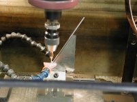
Yes the tubes are 316 SS; the coppery appearance is from the light source during photography.
They were assembled by sliding a pin down the coped tube (the short one) and engaging the hole in the long tube.
They were then clamped together with a little jig to hold the short tube at the proper angle.
They were tacked in a couple of spots on each side and the jig removed.
Then they got a root pass at lower power (220V 3.5 milliseconds).
Then they were smoked to reduce the reflectivity and welded with a hot pass of 235 volts and 3.9 milliseconds.

The machine's maximum output is around 60 watts.
You can control the input energy only with voltage, pulse duration, pulse frequency and spot size as Robin Coope mentioned in a previous post, so I have no idea how much power actually went into these welds, but I'd guess a few watts.

All welds are freehand; aligning the joint under the crosshairs and stepping on the trigger pedal to deliver a string of pulses while moving the part under the beam and controlling its position using the crosshair and watching the puddle.
This is not continuous beam welding; the machine makes discrete pulses; and the pulse frequency for welding was 2 hertz (that's about my comfortable limit for freehand welding; when I've got a part mounted on a slide I'll typically double that).

The tubing is 2.5 mm OD and 1.6mm ID.

A freehand weld like this takes about 5 minutes from when I sit down in front of the machine to when I turn it off again.
Maybe a quarter of that time is devoted to aligning the parts and general farting about.

One thing to be aware of with this machine and this style of welding; it is not tightly controlled in any way.
If these ever go to production, the details of the welding process will be completely different even if it's still laser welded.

First, the shielding atmosphere will be properly controlled instead of just an argon pipe dribbling in the vicinity of the weld area.
Second, the welding parameters will be designed properly to achieve the design specs for the weld and experiments will need to be done and the welds tested and etc etc.
Third, there will be proper fixturing and motion control.
Fourth there will be filler metal added.
And etc etc.

So this job will go to a proper laser welding house with modern equipment and process control and with traceability and all that's needed to certify the parts to whatever standard is required.
I'll be long out of the project by then; my job was to knock something together quickly to do concept testing.

The variables you asked about will all be investigated by qualified laser welding engineers, and yes, as you hinted at, they are all influential so the production welding will likely take seconds, and be extremely consistent with exactly the penetration desired, and the weld chemistry predictable and the physical properties and geometry of the weld predictable too.
Compared to the state of the art, what I've got is pathetically primitive; but it serves me very well so long as I keep all that in mind and don't overpromise the performance of welds done on my machine.

I expect to go through several iterations of the design as we work through all the design issues; typically I'll make a few dozen of various configurations over the next months and then I'll never see it again when it goes to production.

On a completely unrelated note; thank you very much billzweig, for sharing your methods for electroplating tiny parts; I appreciate it very much.
There are so many cool new things to learn...this is SO much more fun than when I was a dentist...sadly not as lucrative though!

Cheers

Marcus
Implant Mechanix • Design & Innovation > HOME
www.vancouverwireedm.com


Back
Top