What's new
What's new

Cost of Production and Confusing Drawing(?)

VTX

Plastic
Joined
Oct 15, 2017
Hello everyone. New to the forum. Not a machinist myself, have a little experience though. First off, allow me to apologize if I'm not posting this in the proper area, wasn't quite sure where to post this. I've attached two screen captures of PDF files because the original PDF is too large to attach, but my questions are: a) How much do you suppose a machine shop would charge to produce four of each part, rough ball-park range? And b) Do you think these drawings are detailed enough; if not, what information are they lacking? I can always add information.
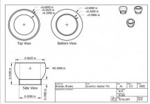
Eccentric Washer Pill.jpgEccentric Washer.jpg

Thank you in advance for any help!
 
It would help if you could upload some large pictures of the drawings. Those are pretty hard to read.

The first step is adding tolerances to the dimensions. All of your dimensions are shown to four decimal places which most associate with higher precision. This might not be the case though.

What the people making it really need to know is if the outer radius of the first part can be between .29" and .31" or .2999" and .3001". That type of thing. You have to determine what the acceptable variance is. One way the people here can help you with that is by telling us how will you inspect the parts when they are sent to you. Are you going to check them with a ruler/scale or a high precision CMM?

Always remember, tighter tolerances mean more money.

This might help you get started.

http://www.toolingu.com/images/finished_pdf_files/800120.pdf
 
on the first drawing you need to define the center of the arc in the axial plane. you have the center mark on there, but no height dimension for it.

You also need to allow for a tool nose radius at the intersection of the outside cylindrical portion and the R0.3 radius. A sharp corner required there will cost you.
 
There are standard ways to create drawings ... we don't just put the views willy-nilly all over the place and label them Top View Bottom View etc. If I saw "axonometric" written on a print I'd laugh myself silly then throw the thing in the garbage, at my age I don't want to deal with buffoons.
 
I think the drawing is fine, and Machinable, other than the center of the radius as Tony pointed out. It is Aluminimnimum. Axonometric is well axonometric, I would laugh about it, but I wouldn't chuck it (I need the work).

Remember it is the job as a Drafts person to make the Print, to a value that is MOST accommodating/interpretable to the person doing the manufacturing, not the smart people who actually know what axonometric is (had to Google it). And to make it most manufacturable within the boundaries of Form, Fit and Function.
 
I think the drawing is fine ...
Eeeuw :D

Remember it is the job as a Drafts person to make the Print, to a value that is MOST accommodating/interpretable to the person doing the manufacturing....
Which is why we have conventions - chapter 3 :

https://maritime.org/doc/pdf/blueprint.pdf

One thing to keep in mind - US practice is to imagine the part under the paper, flip it up and to each side for those projections. European and English practice is to imagine the part on top of the paper, flip up down and sideways accordingly.

Isometric views are extremely rare in simple parts like this and I've never seen one that's dimensioned. Not to say it hasn't been done but it certainly is not common practice.

CAD is gonna have a whole heck of a lot to answer for when it gets to the pearly gates :(
 
The way your dimensions are, the thing is going to cost around a million. 4-digit decimals and no tolerances? How's the machinist going to do that?
At a guess 0.3906" could perhaps be 0.39055...0.39065", because otherwise it would be 0.3905" or 0.3907". But then you could say "no, it has to be exactly 0.3906". Then what?
And so on.
 
Eeeuw :D


snip


One thing to keep in mind - US practice is to imagine the part under the paper, flip it up and to each side for those projections. European and English practice is to imagine the part on top of the paper, flip up down and sideways accordingly.

Isometric views are extremely rare in simple parts like this and I've never seen one that's dimensioned. Not to say it hasn't been done but it certainly is not common practice.

CAD is gonna have a whole heck of a lot to answer for when it gets to the pearly gates :(

There are terms for what you are describing, and even their own symbols, but you knew that, right? :rolleyes5:
 
There are terms for what you are describing, and even their own symbols, but you knew that, right? :rolleyes5:
Adjusting terms for the intended audience ... if he reads the Navy book then grabs some Yuropeen prints (easy to do now that we have the innertubes), he'll think it's all a crock and you can do whatever you want.

But it isn't, and you shouldn't :D

That was the intent, anyhoo .... it's a pretty decent workbook on making drawings (and free), would hate for someone to blow it off because of an unmentioned oddity.
 

Just saying, there is enough information there to manufacture the part. If I threw out every print that I saw, because it wasn't what I expected/wanted....I might have gone the hot dog cart route.

Drawings/sketches on beer coasters, white boards, hand drawn with the sketcher tool and a Mouse, Legos, Broken samples, the list goes on and on and on....

God-Cad really? :vomit:

R
 
Drawings/sketches on beer coasters, white boards, hand drawn with the sketcher tool and a Mouse, Legos, Broken samples, the list goes on and on and on....
Sure you can. But I bet even on a napkin you put the views in the proper place. It's no harder to do it right :)

It's like writing a proposal to the bank asking for money. If you use the proper format you can expect a more positive result.

We learned the basics in high school ... if you took shop as an elective instead of home ec, you learned how to make and read a simple drawing, how to drill a hole, how to ruin a board with a plane, how to not cut your hand off with a table saw ... do we have a couple generations now that don't have any practical knowledge ?

Don't answer that :D
 
Your part depictions do not follow standard drafting procedures. However, except for manufacturing tolerance specifications, the drawings seem to convey a reasonable idea of what you want. I suggest that you talk to a machine shop owner or supervisor that will help you determine what degree of dimensional accuracy that you need for your parts to function as intended.
 
We had 2 years of drafting in HS back in 76 so training is old but general function of the drawing is two fold...

First to perform original design before cad one started with ideas and made the drawings to develop the project then one needs to communicate the layout and form to others

Top, front and side views dimensioned from single edges or other standard forms were common and an isometric view also could be used to allow a different look.

We had as a lesson to draw an airplane that had a delta wing on a boxed body that was tapered from front of wing both ways towards front and rear and tapers were both in vertical and horizontal planes.

The reason was to insure students were able to fully understand each dimension and to translate the intent and communicate the item.

Your drawing communicates what the thing looks like to a potential client or other person only as general look meaning my item looks like this.

To make the item it should have the standard top, front and side views and those are selected as which gives the best details then as mentioned above call outs for radius and tolerances as those details are critical to how the work and QB are done.


Sent from my SAMSUNG-SGH-I337Z using Tapatalk
 
The way your dimensions are, the thing is going to cost around a million. 4-digit decimals and no tolerances? How's the machinist going to do that?
At a guess 0.3906" could perhaps be 0.39055...0.39065", because otherwise it would be 0.3905" or 0.3907". But then you could say "no, it has to be exactly 0.3906". Then what?
And so on.

That is an ASSUMPTION you are making about this drawing. All drawings I have seen that use number of decimal places to convey default tolerances have a place in the Title block where the default tolerances are defined. This drawing lacks that table. Therefore I can make no assumptions about what the number of decimal places means.
 
Thank you everyone for your feedback! I had made a more in-depth reply yesterday, but I guess it never posted. I'm no machinist, definitely not an engineer, and never had the opportunity to take any sort of shop class during my schooling. So my lack of knowledge regarding drawings is evident. I've reviewed some of the material in the references some of you have supplied regarding tolerances and proper views. What I'm attaching isn't a final product, but I'd like to know if it is more akin to what you're used to seeing or would prefer to see. More feedback is appreciated.

Screenshot because the PDF is too large to attach: Eccentric Washer Pill.jpg
 
The .562 dimension is called out twice which is unnecessary and asking for trouble if their is a part revision. (But at least you put the same tolerance on it, unlike the drawings I've been using lately.) Additional I believe that it should be a reference dimension because the diameter at that location and the tolerance are defined by the .300 radius and the radius center dimension/tolerance. I would say the same thing about the redundancy .600 dia dimension and .300 radius, while it does provide clarity one dimension could get missed if you did a part revision. (Once again good on you for making the tolerances match.)

edit: After drawing it in autocad to hit the center of the tolerances (except for the radius center at .313) the top dia came out at .5631 which is out of tolerance. But after a little thought i realized that I assumed that the .562 dia was unimportant but that is for the designer to decide.


Back
Top