What's new
What's new

could use a little help engineering this part

vanguard machine

Stainless
Joined
Dec 20, 2011
Location
Charleston and NYC
trying to figure out what would be the best way to finish this brake lever/foot control assembly for an MC.
Typically i would use a bronze bush here and cut circlip grooves into the main shaft but this is a bit of a reverse engineering thing for a customer using supplied parts.

problem is the peg is threaded onto the shaft and of course would lock down onto the shoulder of the bushing locking it up, of course needs to rotate freely to engage the linkage with master cylinder.
I was thinking a set of thrust bearings on either side of the pivoting arm would be ideal but seeing as how i'm unfamiliar with thrust bearings i figured i would throw it out here for help with the design.

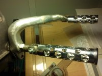
i sketched up a simple drawing to explain what i mean and attached a pic of assembly

open to any suggestions as long as it involves using the customers supplied pivoting arm and peg.

thanks everyone
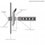
brakeside.jpg
CAM00831.jpg
 
Make two bushings with washer or flanged faces that will fit freely in the brake lever and are a little longer between the faces than the lever is wide when one is put in each side with the flange out. (Picture a pipe with two flanges that is a little longer than the lever is wide, and cut it in half.)

When everything is tightened up, the lever should still be able to move freely (unless you REALLY crank on it). This setup just gives the peg a different face to tighten on to, and transfers that force through to the other side.
 
Use a spacer sleeve on the peg slightly longer than the pedal thickness ,then bush pedal to suit. Spacer sleeve will pevent the peg binding the pedal. I have some MC people I do the odd job for and offten have to redesign thrie ideas into something that WILL work !!
 
one thing i neglected to mention was my trepidation of making a flange faced bushing for this as the hole through the pivot arm is 1/2", so if i made a bushing that was just .125" thick my main shaft would wind up being .25". this is for the rear brakes so a little hesitant to make it that thin.
hope that makes sense.

and shamaj, dont tease!
 
That's a lot of moment on the mount even if the shaft is 1/2 inch diameter.
Has somebody done an FEA on this or signed off on the design?
 
Vanguard,

Forget the thrust bearings. Just put a (pretty) nut on BOTH sides of the sprocket cover. If there's enough shaft length, use thin thrust washers on both sides of the pedal. Educate the customer regarding the shortcomings of the pedal. When the hole in the pedal wears out, is there enough material to bore it out and install a proper bushing (repeat business)?

On edit: My bad. I replied without looking at the photo (only looked at the sketch). The photo scares the hell out of me (agree with Jim Rosen's comment). Is there a bushing inside the bore of the pedal as supplied by the customer? What is the pedal arm material?
 
Jim, this is more or less essentially how HD does it from the factory.
the hole through the sprocket cover, which is designed to hold the mid control pivot, is 1/2".
it's a very short piece so i cant see any problems arising, that said i certainly wouldn't want to make it any smaller, that's for sure.
 
Is there room in the lever to make the hole larger?

You could get away with a lot less than 1/8" wall thickness. I'd be very happy with 1/16", and thinner would work.
 
You really don't need to have a bushing wall that's 1/8, it reduces an already small diameter pivot shaft. If you get even .030 of wear in the bushing you'll notice how sloppy it is and the customer will (should) want it replaced. As such, a .025-.030 wall should be enough for the bushing. You can even bore the bushing housing to the next nominal size if you wish. I would suggest NOT using oil impregnated bronze for this application, though it may seem ideal. I've done this with several shift/brake links on my bikes and feel that it wears out much sooner than I'd like it to. An alum/bronze alloy (Ampco type) would be great for wear but will need a grease fitting. I think that 2 thrust bearings is way more than you need considering the frequency/range of a low speed mechanism like this. The location will also catch a lot of road grunge, not good for bearings. A bushing is easier to clean/disassemble/lube. Hope this was of some help.
 
You are going to need to either thread the casing or step the shaft so you get positive engagement between your threaded 4140 shaft and the casing. If you step the shaft, size it so you can use a thin metric DU style bushing and bore the lever to press fit the bushing in the lever. Add a second step vs. a spacer for the peg mount and you have less moving (wearing) parts to deal with and a stronger mount. 3/4" material will give you plenty to drill / tap for the peg. Turn down and thread from there.

I don't think using the nut to compress everything from the casing wall to the peg mount is going to turn out well and I suspect it will wear out the casing bore pretty quickly.
 
I'd remake the whole shittery and do it right. That whole assembly looks like crap. Don't try and fix garbage with more garbage
 
I have set here and stared at the assembly for a bit now.

You can't change any diameters by enough to enable decent shoulder diameters and case doesn't look like you have much to bore out
of before you get stupid close to the casted ridges.

Bronze thrust washers or bearings could work but some thought needs to be put into it because you of course want Vanguard MC designs to be bullet proof...you know, whole word of mouth thing.

Either bearing or washers are gonna need to maintain the correct spacing (load?) or the brake pedal will bind or feel sloppy.

Can you stand to move the brake arm away from the housing by at least 3/8 of an inch?

If you can then that would allow a jam nut to go between the brake arm and casting so you can secure the brake arm shaft
solid to the case.

Then use the foot pedal and its jam nut to set load on the brass washer.
 
This is how H-D did it on my bike. The shaft is larger where it goes though the aluminum brake pedal. There is a very thin wall bushing in the pedal. The foot peg clamps onto a smaller diameter splined section. The shoulder prevents the foot peg mount from binding the pedal.

HD Brake Pedal.jpg

In your case I think you need to bore out the pedal and make a spacer a tiny bit wider than the pedal to prevent the pedal from being jammed if the nuts get overtightened. This should not require permanent mods to anything except the pedal.
 
This is how H-D did it on my bike."

There's not much for scale in that photo but my guess is
that the shaft from the footpeg to the case (that the pedal
rides on, inboard of the peg) is around 5/8 or so. It's also
probably a forging.

That's not inconsistant with a half inch hole in the case. Just
because the hole's half inch that doesn't mean the footpeg
shank is.

The peg is what, an inch out based on the spacer there. Do the
test: put a half inch diameter piece of steel in the vise. Stick the
end out three inches, and put half your weight on it - to be fair
jump on it as though you were going over a curb on the bike....

I don't want this to devolve into a CF like the time the guy showed up
here and wanted to build the same thing for his bike out of knurled brass,
around the same size. Not my intent at all.

The footpeg on my DRZ-400 has a *lot* less meat in it than these - but
the assembly (including the brake lever) is engineered a lot differently.


Back
Top