What's new
What's new

Delta 15-350 variable speed drill press wiring question

joem64

Plastic
Joined
Nov 12, 2013
Location
new jersey
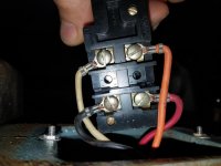
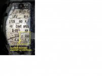
I picked this drill press up from a yard sale and am having trouble re-wiring it for 240v. I've attached pictures of the wire bundle going into the motor case (6 wires), the wire bundle going towards the on/off switch (5 wires) and the wiring diagram on the motor plate. I'm trying to connect a 4 wire pig tail to these wires. I understand that Line-1 and Line-2 are the hots (black and red from plug) and green to ground is obvious but how to a wire the white from pigtail? I read "insulate" orange black and white" but from where? There is orange black and white wires coming from the on/off and the motor housing. Does that mean join them all together to the white neutral coming from the pigtail? Any help would be greatly appreciated.

delta drill wires to on off switch.jpgDelta Drill wires to motor.jpgDelta drill motor plate.jpg
 

Attachments

  • Delta Drill wires to motor.jpg
    Delta Drill wires to motor.jpg
    84 KB · Views: 673
The plate on the motor refers only to the wires coming out of that hole in the motor. The switch shoud be a double pole switch for 240, to disconnect both sides of the line, because both sides are hot. On one side of the switch ( the line side) is the power cord with the third green wire grounded to the machine. The other side of the switch (the load side) has the wires coming from the motor. One load side terminal should have red and blue from the motor. The other switch terminal gets the yellow from the motor. That leaves orange, blue and white coming out of the motor. Tie them together with a wire nut and for good measure you can wrap it with electrical tape. I hope this helps.


Sent from my SM-G900V using Tapatalk

Thanks for your help. I'm drawing your thoughts out with crayons essentially and one part I got confused with. You said "One load side terminal should have red and blue from the motor."

and then-

"That leaves orange, blue and white coming out of the motor."

Blue is being used on one load side terminal so it would not be available to twist together with orange and white.

Could you clarify please?
thanks,
Joe
 
IMO the first step should be to carefully draw out how it is wired now. That should make it easier to understand the changes required for 240v operation. Those photos of wires going through holes don't really give enough information.
 
Oops!! That is orange BLACK and white tied together. Just look at the 240 diagram on the motor plate. Red and blue are tied together on one switch terminal . Yellow is on the other terminal and the three remaining wires are tied together and connect to nothing. Just look at the diagram on the plate for 240. When the switch closes, red and blue get power through one switch contact and the other side of the line is fed through the switch to yellow. That leaves three wires tied together with a wire nut. The terminals on the switch that do not have a line cord on them are the terminals that get ( red and blue) and yellow. I am trying to say it every way I can think of.

Sent from my SM-G900V using Tapatalk
 
IMO the first step should be to carefully draw out how it is wired now. That should make it easier to understand the changes required for 240v operation. Those photos of wires going through holes don't really give enough information.
There are six color coded wires coming out of the hole that match the wiring instructions on the motor plate EXACTLY. If they were hanging loose that would not be a problem. If someone does not understand what is on the plate, they should probably get an electrically savy friend to help. That is 240 and you don't want to let the magic smoke out of the motor.or electrocute yourself. If you have worked with motors you are not trying to see where each wire goes in the photo.

Sent from my SM-G900V using Tapatalk

I was not referring to myself but to the OP, whose level of knowledge is not known and I assume somewhat limited since he already possesses the motor diagram but still seems to require help. I would have had it rewired in less time than these back-and-forth posts take.

In my experience those not skilled in electrical wiring generally do better with a pictorial hookup diagram rather than a schematic. When I create documents for the assembly personnel I must provide pictorial diagrams because few of them can read schematics.
 
Thanks for your help 6PTsocket, it is true that I only have a basic understanding of electrical wiring and your posts helped clarify the whole of the parts.. switch / motor / line-in. The last thing that I'm struggling with is the supply neutral. I've attached 2 pics of the drill switch pulled out of it's case. The back is marked "Line" and "load". Does the line side of the switch receive the 2 hots black and red from the power source one each to either side of "Line"? The load side would then be obvious to me (I think?) However I don't understand where the Neutral from the plug (power source) would connect.
thanksdelta drill 2 pole switch.jpg
 
Ok,

As I see it, the switch is connected the black (hot) to a red wire that is part of the motor group and the white wire (neutral) to an orange wire that is part of the motor group.

Since the low voltage (120v) diagram shows the red and orange connected together as part of the Line 1 group I assume either that these wires (red and orange) connect to other wires that are part of the separate groups for Line 1 and Line 2 or someone has miswired things in the past.
-----------------------------------------------------------
Per the motor diagram what you should have for 120v is:

One wire of the line cord connecting to one of the LINE terminals on the switch with the corresponding LOAD wire connecting to the "Line 1" group of motor wires (blue, red, and orange).

The other wire of the line cord connecting to the other LINE terminal on the switch with the corresponding LOAD wire connecting to the "Line 2" group of motor wires (black, white, and yellow).
-----------------------------------------------------------
To convert to 240v you must remove several motor wires from the Line 1 and Line 2 groups and connect them together as a group that connects to only itself.

You need to remove the orange motor wire from the line 1 group and the black and white motor wires from the line 2 group. Connect these three wires together and insulate them.

Now what you should have is one LOAD terminal of the switch connecting to the blue and red motor wires and the other LOAD terminal of the switch connecting to the yellow motor wire only. The other 3 motor wires (orange, black, and white) connect only to each other.

If the motor runs in the wrong direction swap the black and red leads.
 
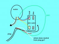
Thanks for your help. To help clarify I drew up a diagram of the motor/switch/line-in. Could I ask you to complete the connection?
I understand where the 6 motor wires need to go. Also the load side of the 240v switch. My confusion is where to connect plug wires. The 2 hots and the neutral. I numbered the line side of the switch (1 and 2) So is it Red connects to 1 and black to 2 if so where does plug white neutral go? Or is it Red and black from the plug twist together and connect to 1 while the neutral connects to 2? Thanks for any help you can offer in advance.

motor sketch.JPG
 
Thanks for your help. To help clarify I drew up a diagram of the motor/switch/line-in. Could I ask you to complete the connection?
I understand where the 6 motor wires need to go. Also the load side of the 240v switch. My confusion is where to connect plug wires. The 2 hots and the neutral. I numbered the line side of the switch (1 and 2) So is it Red connects to 1 and black to 2 if so where does plug white neutral go? Or is it Red and black from the plug twist together and connect to 1 while the neutral connects to 2? Thanks for any help you can offer in advance.

View attachment 201597

In your 240v line cord normally the black is used as Line 1 (L1) and the red as Line 2 (L2). These are both HOT, have 240v between them and should never connect to each other. These are what connect to the LINE side of the switch. One of them will also connect to one side of the work lamp if one exists. The other side of the lamp connects to the white or Neutral. The green is a safety ground that connects to metal parts to shunt away any leakage currents from motor windings and other sources.

The ONLY place the neutral should go in a tool wired for 240v is one side of the work lamp if one exists. The other side of the lamp can connect to either "hot" wire.

What you have in a 120/240v single phase electric source is a 240v transformer with a tap in the center so two 120v branch circuits exist. The center tap is connected to ground/earth at the service panel and becomes the "Neutral". What this means is that there is no shock potential between this wire and earth ground. This is a relic of the old days when outlets were 2-wire and metal housings were connected to the neutral. As a kid I remember more than one phonograph with a non-polarized plug that would give you a "tickle" (shock) when touching exposed metal like screws if plugged in backwards. Some people were killed if they touched a hot chassis along with something like a water pipe.

If you look at a 240v service panel you will see two rows of circuit breakers. One side is connected to Line 1 and the other to Line 2. The 120v loads they serve return current to the transformer through the neutral. High current loads like stoves and water heaters connect to both lines (240v) and do not use the neutral except in the case of 120v accessories such as lamps (in the case of a stove).

In the case of a 120v device Line 1 usually refers to the HOT or black wire and Line 2 to the NEUTRAL or white wire.

In a 240v device both Line 1 and Line 2 are HOT. You should have 240v between the black and red cord wires and 120v between the white wire and either the red or the black wire.

I hope this helps rather than confuses.
 
ahhh now I think I understand...so cap off the white neutral from the plug. Connect plug 120v red to line-1 and plug 120v black to line-2 of the switch diagram (or vice versa depending on which way I want the motor to spin) is that the idea?
Thanks for your help.!!
 
ahhh now I think I understand...so cap off the white neutral from the plug. Connect plug 120v red to line-1 and plug 120v black to line-2 of the switch diagram (or vice versa depending on which way I want the motor to spin) is that the idea?
Thanks for your help.!!

No. The motor direction is controlled by where the black and red leads from the MOTOR go. They have nothing to do with the black and red leads from the CORD. Your diagram is almost complete. I would connect the black from the CORD to the switch "Line" terminal marked "1" in your sketch and the red from the CORD to the terminal marked "2". I suggest this only to follow convention. It will still run in the same direction if you connect red to "1" and black to "2".

Since you have no lamp just tape up the white CORD wire so it can't short to anything.

What you want to end up with is 240v from the line cord connected to the LINE side of the switch and the LOAD terminals connecting to the appropriate motor wires as in your sketch. In the odd chance that it does run backward interchange the black and red MOTOR wires. If you need further help with that, post again after trying it per your sketch.
 
Many thanks for everyone's patients walking me through this voltage upgrade.

I'm in the process of switching all my power tools to 240v where possible now that I have sufficient power to my shop. I have another challenge converting a vintage Kalamazoo horizontal band saw from 120v to 240v.
The motor wiring appears to have been altered evidenced by the wire diagram having been scratched off the plate where it would show how to wire it for 240v. Attached is a pic of the motor wire diagram that shows the scratches also attached is a drawing of how I found the motor to be wired vs. how it suppose to be wired for 120v. I'd like to wire it for 240v but wonder if the changes that were made (I don't know the history) for 120v suggest that wiring it for 240v is not possible...
Westinghouse horz band saw date plate.jpgwestinghouse motor wiring hortz band saw.JPG
 

Attachments

  • Westinghouse horz band saw date plate.jpg
    Westinghouse horz band saw date plate.jpg
    93.1 KB · Views: 396
  • Westinghouse horz band saw date plate.jpg
    Westinghouse horz band saw date plate.jpg
    92.9 KB · Views: 221
Many thanks for everyone's patients walking me through this voltage upgrade.

I'm in the process of switching all my power tools to 240v where possible now that I have sufficient power to my shop. I have another challenge converting a vintage Kalamazoo horizontal band saw from 120v to 240v.
The motor wiring appears to have been altered evidenced by the wire diagram having been scratched off the plate where it would show how to wire it for 240v. Attached is a pic of the motor wire diagram that shows the scratches also attached is a drawing of how I found the motor to be wired vs. how it suppose to be wired for 120v. I'd like to wire it for 240v but wonder if the changes that were made (I don't know the history) for 120v suggest that wiring it for 240v is not possible...
View attachment 201632View attachment 201629
It is possible that the missing terminal was tied to the terminal that the black wire is on now, as a convenience, so you would not have to put two wires on the same terminal and was later just eliminated. The crossing out was probably some user trying to make sure that the motor was only wired for 120. The 2 jumpers suggest that it can be wired for 240. There are two main windings and they are wired in parallel for 120 and in series for 240. Those jumpers put them in parallel If you remove the jumpers you will read some resistance, maybe 10 ohms, across the top two terminals and the same across the botton two. For 240 operation the two windings wil be in series so there will be one jumper with the power cord on the other two terminals but there are several ways to miswire it so I suggest you research the model number to get the plate info or call Kalamazoo.
Many thanks for everyone's patients walking me through this voltage upgrade.

I'm in the process of switching all my power tools to 240v where possible now that I have sufficient power to my shop. I have another challenge converting a vintage Kalamazoo horizontal band saw from 120v to 240v.
The motor wiring appears to have been altered evidenced by the wire diagram having been scratched off the plate where it would show how to wire it for 240v. Attached is a pic of the motor wire diagram that shows the scratches also attached is a drawing of how I found the motor to be wired vs. how it suppose to be wired for 120v. I'd like to wire it for 240v but wonder if the changes that were made (I don't know the history) for 120v suggest that wiring it for 240v is not possible...
View attachment 201632View attachment 201629


Sent from my SM-G900V using Tapatalk
 
It is possible that the missing terminal was tied to the terminal that the black wire is on now, as a convenience, so you would not have to put two wires on the same terminal and was later just eliminated. The crossing out was probably some user trying to make sure that the motor was only wired for 120. The 2 jumpers suggest that it can be wired for 240. There are two main windings and they are wired in parallel for 120 and in series for 240. Those jumpers put them in parallel If you remove the jumpers you will read some resistance, maybe 10 ohms, across the top two terminals and the same across the botton two. For 240 operation the two windings wil be in series so there will be one jumper with the power cord on the other two terminals but there are several ways to miswire it so I suggest you research the model number to get the plate info or call Kalamazoo.


Sent from my SM-G900V using Tapatalk
After thinking about it a little more. Try removing both jumpers. Install one jumper diagonally upper left to lower right or upper right to lower left .It should not matter which. Now put the power cord on the two remaining terminals. Again, it does not matter which gets black or white.

Sent from my SM-G900V using Tapatalk
 
Thanks for your help... do you mean switch one jumper "upper left to lower right" like in the drawing (a to d)? I labeled the terminal posts if it helps.

Also after pulling off the jumpers and being able to see clearer I found the coil wires attached to post c and d. Not sure if that's any help.

thanks.westinghouse motor wiring.JPG
 
Not quite. Move that power,cord wire off d and put it on b. If I am correct, with all cords and jumpers off you should read coil resistance between a and b and also between c and d. You want to put these two coils in series. The current flows from one leg of the power cord into terminal c., through coil cd, through the jumper, through coil ab, and out the other power cord wire on terminal b. I think we detirmined that terminal e does not exist.

Sent from my SM-G900V using Tapatalk


Back
Top