What's new
What's new

Dreis & Krump Chicago Pan and Box Break Refurb Q's

Boxcar

Plastic
Joined
Jun 30, 2014
Location
Florida Panhandle
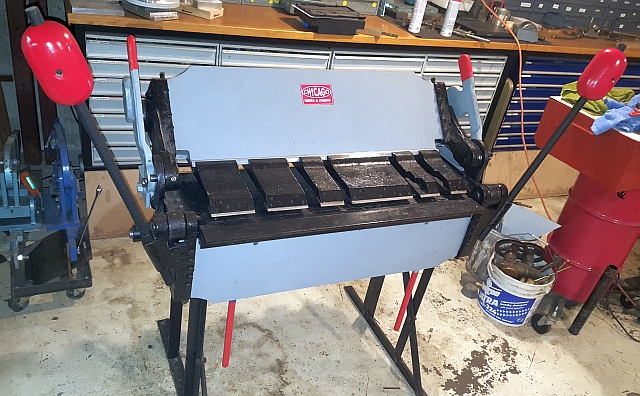
I recently picked up this old break...saved it from a metal recycler business.

145635.jpg


Before there's any confusion... The picture of the rusty one is mine and I had already stripped off the easily removable parts before I moved it.

Was lucky to have found it nearly complete... So far, I believe I'm only missing a part of the apron (If my nomenclature is correct... the assembly that rotates and provides the force to bend)There's an angle channel that is missing.. it's bolted to the face of the apron when attached. While the unit was very complete I do find it odd that it was the only thing missing. All the fingers are present, counter balances, and some misc. parts that I have yet to figure out what they are.

Two questions... and as I'm not at the machinist level... please bear with me.

1. The individual fingers are comprised of a few different parts... my question on that is that there seems to be some painted surfaces and some not. I did a complete teardown of mine before I dropped off to the sandblaster. I'm looking for guidance on what to repaint and what to not paint. Please allow me some latitude in presenting my own naming convention to the parts of the fingers as I describe my thoughts of painted surfaces and non-painted. First: the nose of the finger should not be painted (at least not on the bottom as it contacts the steel that is being held for bending) However, as for the top of the nose...mine appears to have been painted originally and was gone over with yellow thru the years. Thoughts? could keep the entire nose paint free and dress up the steel to a machine like finish.
Second: The largest section of the assembly... I'll call the carrier. I'd say the top and the sides could be painted but as the bottom side comes in contact with the sheet steel.. I'd guess no paint there. And finally, there's a aluminum block that I'll just clean up and assemble as is. Thought's/considerations with regards to the fingers?
152817.jpg
not mine, example only
213715.jpg
not mine, example only

Second topic... with regards to the missing apron component. I'd guess that a replacement to this part could be costly (I'll be checking with Dreis & Krump next week... But could there be a more local alternative that I can cut/fit/drill myself. Would this be a specialized steel? What type? I have some metal specialty businesses near that may have something providing it's not too unique.

145650.jpg
mine, shows the missing L channel on front of the apron
152806.jpg
not mine, shows the channel in place on the apron.

Pics below...thanks in advance for helping/taking the time to look this over.

Finally... I mulled over how the hell I'm going to handle moving this around during the refurb/placement phase... lucky to have a few aircraft roller lying around the shop...cut them down and mounted to a sacrificial board...worked good so far...handles the weight just fine...each roller can handle over 1600lbs each if memory serves me correctly.

082407.jpg

102920.jpg

I'll probably burn for this but... I was in a rush to pick the brake up and get it to the blaster/painter. While I did want to make some brackets to mechanically fasten the rollers to the plywood... I didn't have the time or hardware to get it done.... SOOO, I glued and nailed some blocks in that secured the rollers to the plywood cart. There was a small lip on the roller conveyors that enabled me to simply catch with the blocks... a temporary dolly for sure.
 
The missing apron piece is just angle iron. You can get it at any steel supply shop. A 3x3x1/4 is what I remember being on it..atleast that's what's on my 10 footer.. any area on the fingers that touch the steel being bent is unpainted so it don't leave paint smeared on your work.. I would be interested in your brake if you wanna sale it.. if so let me know 765 499 1875
 
The missing apron piece is just angle iron. You can get it at any steel supply shop. A 3x3x1/4 is what I remember being on it..atleast that's what's on my 10 footer.. any area on the fingers that touch the steel being bent is unpainted so it don't leave paint smeared on your work.. I would be interested in your brake if you wanna sale it.. if so let me know 765 499 1875

It's 3x3x1/4" with one leg sawn down. That is important in this case, as to achieve maximum rated capacity, you have to have the piece of angle clamped into the insert bar position, NOT bolted on the front.

Open this link, scroll down to page 10, and look at figure 19A, to see what I'm describing. Note that yours (just like mine) is what is shown in figure 19, not what is in 18. They call it 'optional construction.'

http://www.sterlingmachinery.com/me...icago-dries-and-krump-hand-brake-brochure.pdf

The literature linked shows that the brake capacity is reduced 4 gauges if the angle bar is removed and the 1/2" nose bar(what yours currently has) is used instead. Note that your angle bar also has holes in it, so it can be bolted on the front with 5/8" bolts. I don't have it with me right now, but in storage I have a copy of the manual for my machine, and IIRC it claims that with the angle bar bolted on the front, you derate the machine 2 gauges.

The allen screws that hold the insert bars in turn clockwise (as you face the machine) to loosen. Most of the ones on my brake have broken (it gets a lot of use), so I use set screws and jam nuts to replace them - simply thread the jam nut onto the set screw, weld it in place, grind the nut round (the tips of the flats hit something on the back), and thread them in from the back.

On mine, the finger nose bars are completely bare, as are the aluminum clamp blocks. Entire rest of the finger extension, finger clamp bar and wing screw are yellow.

These machines hold their value very well and are in very high demand. Since yours is complete, it's worth restoring, as long as it isn't tweaked. Don't short yourself on sale price if you do let it go.

4' length, I'm assuming? Does it have a model number plate still?
 
JLM...thanks for the comment and info. Good, so I did the fingers correctly. I got some updated pics I'll post...stripped it down completely, broke down the fingers and detailing them up now. I'm going to have to keep it for the time being...can't wait to work with it.
 
Fish On... One leg sawn down...hmmmm, I'll look at your references to understand that one.

AWESOME info, thanks so much. I will sure to study it as my restore continues.

I am very pleased with what I'm starting with.. Have yet to validate how tight I've got a small letter and number metal stamp set that I can transcribe the info over with to make a new one and attach all to a freshly painted machine. I need to figure out the year of mfgr yet. Here's new pics.

Sandblasted, Neson 2pt epoxy primer, and Ultra-Thane 2K topcoat. Yellow is the next color to shoot. Used a TIP turbine HPLV system (Great "no-brainer" system)
194532.jpg

r90_194504.jpg

194439.jpg

For the fingers...I had broken the units down so all the components could be cleaned. I knew I was going to have to dress them up so they got blasted as well.
125551.jpg

095813.jpg

194541.jpg

The sides that touch the metal sheet is a machine finish...no paint
194541.jpg

My choice for grey is that I plan to buy some more vintage metal tools and decided that grey will be a good standard color for me.
I have to clean up the aluminum blocks yet and allen bolts...also have a broken bolt to remove or drill out and re-tap...little tasks.

Another small detail... I opted to remove the data plate and name badge before sand blasting... there was oxidation lying under the remaining paint layers. A complete strip down was what I was going for...now I have to reapply those.

I did decide to paint out the entire finger extension to save me some rust abatement...the only area that could possibly contacted the work appears to be the angled area which mine were individually stamped 1 thru 12. I suppose my work contact with that area will be minimal if ever...but not sure. Next, I have to strip the aluminum nose clamp bars as shown in fig. 19A in the linked Mfgr. product guide.

One modification (addition) I've made so far is the lower horizontal L channel...3/8" x 4" x 3". After my initial assessment of the machine I noticing how the fingers had worn the upper assembly surface (paint) as operators would hang unnecessary fingers along the top. I decided that all the $$ spent on refurbishing this piece of equipment justifies another storage option. I welded in the large channel to act as a carrier for the fingers thus avoiding future wear. I did ensure that the channel was far enough back to clear the bending leaf even if the channel is loaded with unused fingers... thoughts??
 
Nice job! Congratulations on finding a fine old machine. I used to own what I believe was a model 412 finger brake.

weightsInstalled.jpg


Mine was missing a finger or two, whereas yours isn't. When I sold mine I got interest from all over the country. Be aware that the older they are the scarcer they are. In the years I owned mine, I only found one other machine like it. Mine is clearly older than yours; it's fingers clamp in the back, not on the front like yours.

The Chicago 'nameplate' on mine was just a decal made up from an online scan. But it looks real good.

You can see some shots of mine as well as how I designed and made the counterweights on this little blog: (link below)

metalmagpie

http://nwnative.us/Grant/shop articles/fingerbrake/counterweights
 
Fish On... One leg sawn down...hmmmm, I'll look at your references to understand that one.

Actually, I was mistaken, it's not just 1/4" angle with a leg sawn.

It's actually multi thickness. The long leg is 3 x 3/8" (standard American standard edge). The other leg is 1 7/8" x 1/4". It has a square edge (sawed or milled). I don't know the availability of multi thickness angle, so if you were making one, you'd probably just have to use 1/4" and call it good.

IMG_3060.jpg


Yours is currently set up like this. It has what is called the 1/2" insert bar. In this configuration, you derate the machine 4 gauges.

IMG_3065.JPG


The angle bar has 4 bolt holes in it (mine is a 6' machine, yours would have 3). This allows the angle bar to bolt to the front of the leaf with 5/8" bolts. I don't remember the numbers, but in this configuration, I think you derate the machine 2 gauges.

IMG_3068.JPG

IMG_3066.jpg


Now, if you remove that angle bar, and the 1/2" insert bar, you'll have this. The insert bars are removed by turning the visible allens clockwise, just 1/2 - 1 turn is fine, they are just clamp screws.

Note the stepped insert bar shape. A 1/4" insert bar is also available (or can be shop made from 1/4" flat bar) for even closer reverse bends. That reduces the machine 7 gauges.

IMG_3070.JPG

Next post.
 
To achieve the full rated capacity, you have to put the angle insert bar into the top position. Hence the reason for the sawn edge.

IMG_3073.jpg

IMG_3074.JPG

The allen screws you use to clamp the insert bars in place are just set screws with something welded to them, threaded in from the back. I've broken all but one of the originals on mine (seen on the left), though when I pulled it out to take a photo, I noticed that it is starting to crack.

The originals just had a little dished washer or something welded on. I used a slightly longer set screw, threaded a jam nut on, and welded it on (does require knocking the points of the nut off slightly to clear).

IMG_3076.jpg

IMG_3075.jpg
 
Fish On... I'll get back to you soon on this. Until then Thanks for taking the time to educate me on this machine. You've went above and beyond Sir!
 
Metalmagpie....thanks for the perspective. Your tech article on your weights was very inspiring, thoroughly enjoyed that. great job. 32' was an awesome year...I could see a fella bending metal "For his NEW 32 Ford Roadster... equipped with the newly introduced Ford flathead V8!!!!"
 
The rod is part of a stop assembly for doing repeat bends. It would have been straight when it was new, but I've never actually seen a straight one in the field.

As far as the angle goes, I have a very similar brake with the same nose bar setup. The angle the came with mine isn't factory and attaches to the front edge of the apron with three 5/8" bolts. It's a 3" x 3" x 1/4" angle, but the holes are drilled such that when it's on the face of the apron, it's flush with the top and contacts the material being bent first, giving you the full rated capacity of the brake. I haven't taken the 1/2" nose bar out of mine since I've owned it, and I only put the angle on if I'm doing radius bends or material thicker than 18 gauge (I have a 14 gauge rated brake).

The angle serves two purposes. It stiffens the apron, but it also gives additional leverage because the edge contacts the material first. It does make the bend less sharp, which can be an advantage or disadvantage depending on the situation. The main issue is it increases the minimum reverse bend you can make, which can be inconvenient. It's surprisingly easy to come up with a combination of bends you can't do!

Your restoration looks great. I need to do something similar to mine someday...
 
I'm slowly educating myself on the break through these posts and I did get an operators manual from the company this week...have yet to digest it all. While I was at it I ordered up a few missing bits... hope to have a "significant" update pic to post by the end of this weekend. Any thoughts with mounting these brakes to the floor or not... Considering it's heavy as hades.. and it will experience occasional use vice production work. I'm pondering the "bolt down" vs "footloose"
 
Any thoughts with mounting these brakes to the floor or not... Considering it's heavy as hades.. and it will experience occasional use vice production work. I'm pondering the "bolt down" vs "footloose"

I don't see a need to bolt them down. Mine has been on wheels (albeit cheapies that don't roll well) since the day I bought it, and it is used daily for semi production work.

I built a set of these when I first bought it. 3.5x5x.25" unequal leg angle, and some $4.99 wheels from Northern (bronze bushing, not ball bearing). As you can see, when I built it, I put coupler nuts on it, intending to use them as brakes/levelers. Years later, I've never actually used those once, though with better wheels, they may have been needed.

DSCI0365.JPG

I agree with Graham that the other two pieces (aside from the stop rod), don't go with the machine. Or, if they do, I've never seen them before.

Here's how the stop rod mounts.

IMG_3089.JPG

IMG_3088.jpg
 
I have a smaller DK box and pan brake, 14 gauge. Definitely a bolt solidly down to the floor tool for me. I'm surprised the larger brake doesn't need to be secured to the floor.
 
Thanks again for the information...those roller skates you fabbed up are really nice...you got me thinking of what I have lying around (don't have a big material benchstock yet.

Thanks also for the Stop Rod info...you would figure I find out its bent after its painted.

Thanks guys.
 
Getting close to the final stretch... Guess wrap up will be next week.
164717.jpg

164733.jpg

164745.jpg

...and the award for the most awkward part to paint goes to....this damn thing
175921.jpg

finally got the opportunity to break out an early set of brass stencils.
181609.jpg

I've got a few hours on these...hope it shows
184330.jpg

All together again.
184347.jpg

190720.jpg

AND not pictured...the former "bent stop-rod"....is now straight, and repainted. More to follow...next week. Waddya think!
 
I had initially removed the plates on the break so I could sandblast the area...figured I'd just refurb the plate and reapply. BUT, they still make'em so what the heck. I took the easy way out.

175312.jpg

Now I've got to drill it and remount it.
175442.jpg


I forget the proper name of the L-channel I was missing but I got it... I decided to eyeball it to determine how straight it was. Well, I could see it was a little off. I got it from D&K. I didn't have any machinist wire but I did have some casting line that I could get real tight... I checked it on two sides and stood it off with a penny on both ends... ( I can hear ya'lls eyes rolling!!!) I'm a 1/16 out at the middle both ways. I don't know the grade of the steel at the moment...unsure if it written on the invoice...but I doubt it. I guessing it's acceptable but I'm interested in any thoughts on the subject. With luck and proper placement of the holes for mounting I may be able to pull it out OR I make it worse either are possible outcomes with me....but I try.
185532.jpg
 
Some movement on this project yesterday..
Finally moved in place and light assembly. I have a couple of clean-up tasks but I'm forced to do some shop re-organizing before I go any further...it's a wreck.
174810.jpg

174757.jpg


Back
Top