What's new
What's new

Dynamic (Grinding) Wheel Balancing Method using iPhone Vibration App and SHCS's

dgfoster

Diamond
Joined
Jun 14, 2008
Location
Bellingham, WA
I imagine this method is not new, but it is new to me and has proved useful and could be used for other wheels besides grinding wheels.*
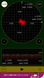
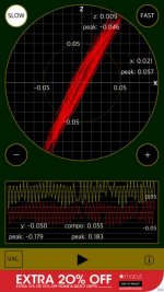
I think the pictures pretty much tell the story of what I made. One tool that really help figure out weight placement was a free iPhone app (Vibroscopelite) that allows the user to quantify vibration by just putting the phone in contact with the spindle housing. That allowed me to try SHCS's in various positions around the wheel measure resulting vibration. It was not that tedious to virtually eliminate vibration in the wheel; see screen shots of the app showing relatively large deflections vs. the "bullseye" pattern that measured vibration that was barely palpable to touch when the wheel was balanced. These images will be in my second post.

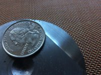
I found that the SHCS's by themselves did not have quite enough mass to balance the wheel, so I made the steel segments shown to augment the screws. The 2-hole segments are the same weight as two SHCS's and the 3-holes equal 3 screws.

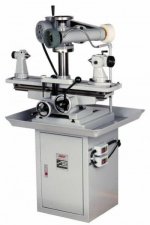
* Background info that not everyone may care to read: The problem I was experiencing was vibration in my tool and cutter grinder when using various grinding wheels particularly a 7" Type1 wheel. The vibration caused some surface finish problems when I was grinding tapers for a "tuned up" ER collet spindle I was making.

My vintage Enco T+C Grinder is very versatile, but the cost of that versatility is structural flexibility (springiness) of the machine when compared to the relatively stiff structure of my Harig surface grinder. The need for wheel balancing on a surface grinder has been much discussed and I think the consensus is that it is not usually needed. And on the T+C grinder for just grinding a lathe cutter or other simple cutting tool, vibration is probably not a practical concern.

When I bought the T+C grinder there were a number of vibration sources including a single phase motor, pulleys not concentric, v-belt drive, and spindle that was full 11thou non-concentric. I replaced the v-belt with a flat urethane belt, turned the spindle between centers, and installed a 3-phase motor. Each upgrade improved performance, but the wheel-induced vibration seemed insurmountable until a friend pointed out the vibration apps available for smartphones. That app is very easy to use and makes quantitative what would otherwise be guesswork. BTW, this was a brand new Norton wheel.

Added later: the SHCS size was 8-32 ---someone asked. They weighed 2 grams each.
:
 

Attachments

  • Tool and Cutter Grind.jpg
    Tool and Cutter Grind.jpg
    23.8 KB · Views: 1,213
  • Wheelbal2.jpg
    Wheelbal2.jpg
    63.8 KB · Views: 2,900
  • WheelBal1.jpg
    WheelBal1.jpg
    52.8 KB · Views: 1,899
  • Wheelbal3.jpg
    Wheelbal3.jpg
    72.7 KB · Views: 1,385
  • Vibration1.jpg
    Vibration1.jpg
    10.3 KB · Views: 902
Last edited:
Here are a couple of screen shots of the app output. The vibration measured in the wheel prior to insertion of any SHCS's was considerably worse than the "bad" left side image shown.

Measurement prior to spindle turning, motor replacement and pulley mods would have been off the charts.


PS: I added an image showing the slitting of segments using the pre-drilled holes as index stops.
 

Attachments

  • vibration2.jpg
    vibration2.jpg
    72.8 KB · Views: 1,041
  • Vibration1.jpg
    Vibration1.jpg
    10.3 KB · Views: 636
  • SlittingSegs.jpg
    SlittingSegs.jpg
    88.7 KB · Views: 1,035
We have some funky work-holding for our lathes that requires balancing from time to time. For lack of better terms, the face-plates have 12 slots & tapped holes around the perimeter to attach balance weights. My crude but effective method is to run up the spindle initially to determine how bad the balance is. Then, attach weights to either the 12-o-clock, or 6-o-clock position. Better or worse? If it's better, then I know I'm adding weight in the right direction. If it's worse, I need to add weight to the other direction.

Next up - Add mores weights. Better or worse?

If more weights make it worse, then I "divide" the weight by moving the two weights from the 12-0-clock position to 11 & 1. Or even 10 & 2. Playing the "better or worse" game the entire time.

In a matter of about 10 minutes, you can get pretty remarkable balance with no tools at all, just by playing "better or worse?"

The same could be done with a surface grinder too. If you made a nut with 12-tapped holes, you could do the same thing. Knowing the direction of the initial impalance helps speed this up a bunch. Mounting the wheel on leveled shaft, and noting the "bottom" position after several tries should point out the direction of the imbalance. Mark it, and line that up with the 12-o-clock position when you mount the wheel, and then start playing the better or worse game...

Although, I've often thought about making a special nut for surface grinders, using lead-shot, or BB's, or whatever, for automatic balancing... It might be worth a shot?

https://youtu.be/ullnFQD4F1I
 
Nice one Denis.

I use an app called Vibration to analyse machine vibrations. The frequency/amplitude graph can be used to identify the frequency at which the vibration peaks occur. By knowing the rpm of the various components in the chain, it enables the component that's causing the vibration in a machine to be identified or at least suspected for further investigation. I've had the app for ages, but I'm pretty sure it was free too.
 
We have some funky work-holding for our lathes that requires balancing from time to time. For lack of better terms, the face-plates have 12 slots & tapped holes around the perimeter to attach balance weights. My crude but effective method is to run up the spindle initially to determine how bad the balance is. Then, attach weights to either the 12-o-clock, or 6-o-clock position. Better or worse? If it's better, then I know I'm adding weight in the right direction. If it's worse, I need to add weight to the other direction.

Next up - Add mores weights. Better or worse?

If more weights make it worse, then I "divide" the weight by moving the two weights from the 12-0-clock position to 11 & 1. Or even 10 & 2. Playing the "better or worse" game the entire time.

In a matter of about 10 minutes, you can get pretty remarkable balance with no tools at all, just by playing "better or worse?"

The same could be done with a surface grinder too. If you made a nut with 12-tapped holes, you could do the same thing. Knowing the direction of the initial impalance helps speed this up a bunch. Mounting the wheel on leveled shaft, and noting the "bottom" position after several tries should point out the direction of the imbalance. Mark it, and line that up with the 12-o-clock position when you mount the wheel, and then start playing the better or worse game...

Although, I've often thought about making a special nut for surface grinders, using lead-shot, or BB's, or whatever, for automatic balancing... It might be worth a shot?

https://youtu.be/ullnFQD4F1I

I used to work a couple lathes down from an old guy who did a lot of face plate work on Babbitt bearings. He had a C-clamp nipped on a hacksaw blade that was secured by a screw into t he head stock. He called it a Wig-Wag. It's function was to detect out of balance with his set-ups by synchrionizing and amplifying the slight motion of the headstock when the out of balance RPM crossed matched resonance . The clamp was adjusted to resonate at 35 RPM or some such figure. If the wprk was out of balance at 35 RPM the Wig-Wag would resonate. Less resonance = less out of balance. He picked that RPM because he could still spot the point of max Wig-Wag yet there was enough RPM to excite it.

I've seen him balance honkin big Babbitt bearings with wide cut outs in the upper half for oil rings slick as a whistle. Some took maybe 30 lb to balance. Old Ray would balance them with his gadget then bore the bearings at 200 RPM. Nobody else adopted the idea probably because Ray ate lunch alone at his machine. He was nervous in a group and made dumb jokes.

Make me wonder how many good ideas were scotched because the originators weren't in the "in" crowd
 
Last edited:
FYI, have done similar with my surface grinder before i had a balanceing spindle (3 years no balanceing spindle, then one lot of wheel adaptors on ebay came with three of the damn things!!!)

I simply use to sit a half thou DTI just on the furthest out point of the wheel head, most surface grinder wheel adaptors have balance weights, then just like you played better and worse, goes pretty quick.

If you want to improve things more, dress the sides of the wheel once you get the balance close, then balance it some more. Once with my setup i found what i called the dead balanced zone, i would try and move the weights and id each side of it i could detect a inbalance using a sharpie marker to define the limits, then set them to the middle of it :-) Realy helped with the dodgy old spindle bearings, but with good bearings, slight imbalance has a lot less effect!

I like the DTI idea as an alternative that would be more quantitative and reproducible than just feeling the spindle.

I am a little confused by your post. Are you talking about balancing spindles or adapaters? Do you think think most smaller (7") surface grinding adapters are balancing? I have not had the opportunity to personally canvas the industry, but my understanding is that most of the time balancing is not done on grinders similar in size to my Harig that takes 7 inch wheels. I too have found that dressing most of the side of a wheel can smooth out a "wobbly" wheel though most of the wheels I have used have been not so far out of lateral trueness for this to make that much difference. I do usually side dress the enough of the wheel to true the part that may be grinding to a shoulder but not for balance reasons.

Denis
 
I like how our tricorders are becoming more useful everyday. There are some pretty good inclinometer apps, that are very accurate that I use from time to time.

Did you notice an improvement in surface finish after balancing?
 
I like how our tricorders are becoming more useful everyday. There are some pretty good inclinometer apps, that are very accurate that I use from time to time.

Did you notice an improvement in surface finish after balancing?

Yes, there was a large improvement in finish. The difference is comparable a dressed SG finish vs. the corrugated "hopping wheel" finish when a SG wheel is out of true.
I attached an example of a scrap of A2 I ground. This finish is not so fine as to cause grinder envy among the surface grinder hands here. But it is a ton better than where I started out. I don't have any good "before" pics---sorry.

(I also find the level/inclinometer apps to be very useful. I've used it, among other things, to calculate the rolling force of a machine being moved down a grade, the height of a waterfall when out on a hike, the slope of various roofs, and use it for non-critical setups accurate to a degree or less.)

Denis
 

Attachments

  • image.jpg
    image.jpg
    20.1 KB · Views: 473
  • image.jpg
    image.jpg
    95.3 KB · Views: 569
You call that an improvement? Any 7 inch wheel that is out of balance enough to affect finish should be replaced. Any wheel that needed the extreme you went to should be shit canned long before that useless effort. I can not see any improvement. I think any improvement is all in your mind. Both those finishes suck . It looks like you are taking a serious depth of cut there. Why not tell us your depth of cut, crossfeed increment , material, and such before you ascribe miracles to something that does not exist and should not be a problem?
 
You call that an improvement? Any 7 inch wheel that is out of balance enough to affect finish should be replaced. Any wheel that needed the extreme you went to should be shit canned long before that useless effort. I can not see any improvement. I think any improvement is all in your mind. Both those finishes suck . It looks like you are taking a serious depth of cut there. Why not tell us your depth of cut, crossfeed increment , material, and such before you ascribe miracles to something that does not exist and should not be a problem?


Hee,Hee. You are right that those finishes are the same. I accidentally posted the same image twice. I was aware of the double post but from my iPhonr managing images can be tricky. You must have assumed one was a before and one an after image.

And you are also right that I would not think the finish very good if I were trying for a good finish with a surface grinder. Remember this was made with a T,+C cutter. Please post your results with your T+C grinder.

I certainly find no fault with the wheel. There is no way they can be perfect and this one was very good. Had this one been mounted in my surface grinder it would have performed admirably as the mass and stiffness of the grinder would have concealed this slight imbalance.

The whole point of the thread was to just let folks know about a method of wheel balancing that might work for them. Not trying to show how wonderful a surface finish can be made on a T+C grinder. I am just pleased that a much better finish could be obtained.

Denis
 
Last edited:
I missed the part where you said you pur your iphone in contact with the spindle housing. I was thinking you touched it directly to the grinding wheel. I was wondering how many test measurements you got per phone. :-)

Seriously, on 7" surface grinders most wheels are held in wheel adapters. None of the Sopko adapters I owned had any capacity for balancing. I ordered some wheel adapters from Chevalier's sales office in LA (Taiwanese, good stuff) which allow balancing by moving weights around. A lot like the way you did it except without all that unthreading and threading. They didn't cost too much, and for sure a wheel mounted in a balancing adapter and then balanced properly worked a whole lot better than one without. In case someone wanted a turnkey solution.

metalmagpie
 
Oh - and I just remembered I once helped reduce the vibration on a drill press by introducing a dynamic damper. This was back in 1998. Here's what I wrote back then:

"The idea is to add a piece to the machine that behaves like a
cantilevered leaf spring with a weight on one end. A flat spring
with one end fixed and a pendulum-like weight on the other end has
a definite resonant frequency. It is possible to "tune" this
frequency by moving the weight in and out slightly. Anyway, if a
machine is being excited by a vibration source and it is vibrating
excessively, if at the point of excitation such a leaf spring-weight
assembly is attached and tuned to the driving frequency, the idea
is that most of the energy is transmitted to the pendulum (the
"dynamic damper") and not to the machine. I designed a small
damper for my drill press, and it does seem to help.

"Here is my design. It can be used as is for drill presses with
NEMA 143 frame motors (3/4" shaft, 4" bolt hole separation in
the direction parallel to the shaft, 5 1/2" bolt hole separation
in the direction perpendicular to the shaft). I made mine all
from 1/8 by 1" mild steel flat bar. I cut two pieces of flat
bar so that they bolted onto the motor mounting bolts, and
had 7" sticking straight down below the motor. This is the
cantilevered spring, albeit split into 2 parts. I then cut
4 pieces 8 1/2" long, and drilled 4 3/8" holes to bolt them.
Starting from an end, the holes are in 1/2" and 2 1/2", so
they straddle the springs hanging down. I cut 1 1/2" pieces
of 5/16-18 allthread, and used nuts and washers to bolt the
4 pieces together, clamping over the springs. All together,
the 4 pieces of flat bar, the allthread, the nuts and washers
form a weight. A weight suspended from a spring forms a
system which has a natural frequency.

"You can "tune" the frequency by adding washers, or by moving
the weight up or down. When I get mine within 1/16" of the
right spot, it really takes off. When it is operating, soaking
up the vibration, I can balance a nickel on the table of my
drill press.

"The design equations were published in a book titled, "Practical
Solution Of Machinery & Maintenance Vibration Problems" by
Ralph Buscarello, pub. 1979. I found this book in the Seattle
Public Library."

Very coincidentally, just this afternoon I bought another old drill press. This one is 1980s Taiwanese, branded "Foremost" but it's a 20" machine with a 3MT spindle, it's all there and there's very little rust. And it was cheap. Rather than flip it and make a few bucks, I plan to systematically work on eliminating the vibration. Don't know if I'll be making another dynamic damper but you never know!

metalmagpie
 
I missed the part where you said you pur your iphone in contact with the spindle housing. I was thinking you touched it directly to the grinding wheel. I was wondering how many test measurements you got per phone. :-)

Seriously, on 7" surface grinders most wheels are held in wheel adapters. None of the Sopko adapters I owned had any capacity for balancing. I ordered some wheel adapters from Chevalier's sales office in LA (Taiwanese, good stuff) which allow balancing by moving weights around. A lot like the way you did it except without all that unthreading and threading. They didn't cost too much, and for sure a wheel mounted in a balancing adapter and then balanced properly worked a whole lot better than one without. In case someone wanted a turnkey solution.

metalmagpie

Thanks. Using a manufactured balancing adapter would be a great solution if only they were made for straight shaft spindle machines. Maybe such a thing exists.

This particular T+C grinder does not have tapers on the spindle as you would find on various machines e.g., Cincinnati. This Enco has straight 5/8" straight spindle ends. I did look through Sopko's catalog and could not find any balancing adapters for straight shaft spindles and for that matter did not find any adapters whatsoever for straight shaft machines. (That could be because it might not make a lot of sense to use an adapter on a straight shaft machine or it could be that I simply missed them in my search.) I did find many tapered socket balancing adapters for 7" wheels typical on many smaller surface grinders which must all have tapered spindles. The design of those Sopko balancing adapters was nifty as they used pocketed washers designed so that the pockets were concealed in use.

Denis
 
Last edited:


Back
Top