What's new
What's new

First time machining 303 and I am lost

Vitran

Aluminum
Joined
Mar 31, 2016
I am assigned a part I have no idea how to make it and would like some advice.
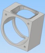
Capture.jpg

There is a 4" bore hole 3" deep in the middle of a 303 block. A round shaft fits inside this and spins with clearance around it. The tolerance I am looking at for the hole is +-.001".

My current plan is to drill through with a 3/4" drill, rough out with a 3/4" long carbide end mill taking 1/2" deep cuts to the bottom, then using the 3/4" to do a facing of the outside of the hole in one pass.

I also think this is a horrible plan. I found that when I machined a prior prototype from steel doing the above plan it chatter like hell due to the cutter length. I found doing plunges with the end mill proved to make no chatter and I left a 0.010" wall to do in a final pass. From what I know about 303, this may not be a solid plan due to work hardening.

My other option I am contemplating is drilling a 1" hole and buying a boring bar set to gradually bore out the hole to the final diameter.

Any suggestions of what I could do?


I'm self taught machinist, mechanical engineer, running a Deckel FP50CC/T with a Dialog 11 controller. I have been using this machine for a few years now and have a solid grasp of how to write code on the machine and some CAM experience. I have Autodeks Inventor's basic HSM, but I haven't written the post processor and the ones online and provided are not correct. I have to do a lot of manual fixes to the Autodesk's output. I have also made post processors for CamBam and a few other small CAM programs, but they do not have HSM tool paths.
 
Whatever you do remember that Stainless is famous for moving,rough it out first then start the finishing process.
Even 2 roughing cycles, rough,rough ,semi finish then finish.
A fixture might be in order also.


We did alot of stainless and sometime we actually roughed it out and let it rest unclamped overnight,
 
I wouldn't go for the weldment because of a huge amount of joint prep required, most of which must be machined because grinding stainless is a bitch, plus the 303 factor is not conducive to welding matchup I suppose, but that's just me. And I like welding :)

I think I'd rough the hole out on a lathe, since I would probably be starting with a piece of round bar (most readily available form). You can make a lot of chips for cheap with a lathe, rather then fretting about using up expensive endmills before you even get to the fine cutting. 4" bore, 3" deep, no problem for lathe tooling, it's perfect.
 
This whole project is a challenge, let alone the 303. I made one out of aluminum and steel in a few parts and used reamed holes and dowel pins to assemble and align them, but my tolerances were still off. I am hoping that by making this out of one block I will remove the tolerance issues.

I wanted to make a few parts and weld them together, but I do not think I can get the alignment afterwards.

The part is for food grade parts so it must to be from a stainless alloy, and overall my confidence in making this is waning.
 
What's your ballpark budget figure for this part? That has a definite effect on how enthused one might be, but it looks like a nice job to me. I've got all the various machine tools needed, with software I can 100% rely on. I don't know if you're stuck with just a small mill or what not.
 
Do not let the 'stainless' part of the material name influence your machining plan. 303 machines more like mild steel rather than 304, and is not particularly susceptable to work hardening, though it can happen.

As above, the material is likely to move as you proceed with your machining so you do need to allow for that.
 
I really feel for having to make this part. I suspect an engineer with zero knowledge of machining designed and assigned tolerances, selected material. The mismatch between designs and builds just kills productivity and does nothing but drive costs out of sight. The end result by the money managers is to source the work overseas and they send us back a plastic part that does the job.
 
I second roughing out the bore on a lathe leaving some for finish. Do all the rest of the work then clamp to face plate on lathe and finish the bore. As far as food grade material goes 303 is not but 316 is. I have had better luck getting quality 316 than 304 FWIW.
 
303 is not food grade,but there are exceptions where it can be used in a plant,but in no way can it have contact with food if 303

303 will pit and slightly rust,especially when "wash down" is common in food plants
 
<SNIP>I also think this is a horrible plan. I found that when I machined a prior prototype from steel doing the above plan it chatter like hell due to the cutter length.<SNIP>

Exactly what I was thinking when I was reading along. I'm glad you've already figured out this part. A larger diameter indexable tool could be used for more tool rigidity and less engagement with multiple passes. This wouldn't be a magic bullet though.

I don't think there are any obvious answers on this one, but there may be some clues to be found on the drawing and/or with any existing sample parts. There's a good chance there is more tolerance for deviation than one would initially think. Someone had to make it in the first place, unless this is a new design - in which case there wasn't enough attention paid to manufacturability.

The main issue I see is rigidity in accurately machining some of those thin sections. This can be overcome by leaving some reinforcing material that will be removed with another operation later, or by adding something (like a plug) that will give you the same (or better) result. Machining the bulk of it then grinding might be an option, but this part's getting real expensive now...
 
I have been in discussion here with the heads about what we can do about this design.

303 was selected as it is for food testing. Not necessarily food grade. From other designs we found, they have aluminum housings. Stainless was selected to have more rigidity and to match the dozens of other stainless parts in the laboratory area this is going. However, that said I was told we can go to aluminum and anodize it.

This is the prototype, but it is based off of some other products of similar nature. The holes in towards the main bore are not tight at all and can be +-.02" if needed.

I am leaning towards using a boring head to make the part. I believe this part can be made that way.


As I mentioned at the start, I am self taught and don't have many others to talk to about the machining and manufacturing. It is good to discuss this with others. Thank you.
 
Another vote for machining the bore first and plugging it for support whilst doing the other operations.

Maybe arrange an expanding plug with a sacrificial alloy tube alternately slit from opposite ends ER collet fashion expanded by a bunch of O rings held between tapered washers clamped up by a through bolt system. Allegedly over 1/16" expansion is possible which should be enough. Sacrificial tube means you can run the cutters into it rather than having to be exact enough to just miss.

Not tried anything like this myself but I have encountered the stack of O rings and taper washers system as past of an adjustable slide up tube stop system. Very firm grip with negligible effort.

Clive
 
Me? I would first finish the thickness perpendicular to the 4" bore and then either rough the outside and 4" bore with water jet or I would finish the outside and bore with wire EDM. After that the rest is pretty straight forward. It all depends on your budget.

Another method would be to make it from round stock enough to put the 4" bore in the center. Do the 4" bore on a lathe and face it to length and have the outside wire EDM'd to finish.
 
The bore doesn't bother me. That is a job for boring, either lathe or mill. How are you planning to do the circular cutout, a rotary table? I would rough out the shape leaving .02 or so for cleanup. Then stress relieve it at 400 - 600 F, then finish. Not going to be a quick job though.

Tom
 
Of all the parts on it, I find the radius on the corner rather easy. I am using a CNC with no manual aspect to it. I have done a few radius like that in the past by programming in the spines and telling the machine to mill out the pocket area with the right surface speed. It is a Dialog 11 interface.

As well, that radius is mostly for show. It can be replaced with a chamfer.

My main concern at the start of this discussion was how to bore the hole. I have had bad chatter with long end mills in the past before doing this stainless. I am now thinking drill a hole, plunge operations with an end mill, then bore the edge surface with a boring bar.
 
Another vote for machining the bore first and plugging it for support whilst doing the other operations.

Maybe arrange an expanding plug with a sacrificial alloy tube alternately slit from opposite ends ER collet fashion expanded by a bunch of O rings held between tapered washers clamped up by a through bolt system. Allegedly over 1/16" expansion is possible which should be enough. Sacrificial tube means you can run the cutters into it rather than having to be exact enough to just miss.

Not tried anything like this myself but I have encountered the stack of O rings and taper washers system as past of an adjustable slide up tube stop system. Very firm grip with negligible effort.

Clive

Been there done that, it will spring once the plug is removed.
I would be inclined to use the threaded holes for fixturing then finish the bore.


Back
Top