Feels like I have gone to the end of the Internet and back and no pictures or discussion of the disassembly of a Hardinge dividing head. I am stuck at the end- removing the spindle. The bearings are still in each end and the front cap, the black plastic part that appears pressed in is still assembled. The spindle lock assembly is out. Any advise on spindle removal from someone who's done it before would be much appreciated. Don't want to damage anything. Called Hardinge they transferred me 4 times then said they'd call me back if/when they found someone who could help. Spindle has some surface rust I wanted to electrolysis off. And I had to see what was on the inside...
How to install the app on iOS
Follow along with the video below to see how to install our site as a web app on your home screen.
Note: This feature may not be available in some browsers.
Largest Manufacturing Technology Community on the Web
Stay Connected:
You are using an out of date browser. It may not display this or other websites correctly.
You should upgrade or use an alternative browser.
You should upgrade or use an alternative browser.
Hardinge dividing head disassembly
- Thread starter m2salmon
- Start date
- Replies 29
- Views 12,858
L Vanice
Diamond
- Joined
- Feb 8, 2006
- Location
- Fort Wayne, IN
Here is the parts list. Note that the universal head has some differences from the plain head.
I have several of the heads, but have never had a spindle out.

This version is more clear.


Larry
I have several of the heads, but have never had a spindle out.
This version is more clear.
Larry
MattRobertson
Aluminum
- Joined
- Apr 9, 2012
- Location
- Nixa, MO
Hardinge also made a manual for their dividing heads.
HARDINGE Plain or Spiral Dividing Heads Instructions & Parts Manual
HARDINGE Plain or Spiral Dividing Heads Instructions & Parts Manual
L Vanice
Diamond
- Joined
- Feb 8, 2006
- Location
- Fort Wayne, IN
Hardinge also made a manual for their dividing heads.
HARDINGE Plain or Spiral Dividing Heads Instructions & Parts Manual
The manual has one page telling how to operate it, with another page of pictures pointing at the various operating screws and such. The rest of the manual is tables for spiral milling on the universal mill and divisions obtainable with the various plates. No use at all for taking it apart, except for the parts list and illustrations that I posted already.
The Hardinge Mill group on Yahoo has a number of downloadable files of Hardinge info and photos. Some member there may have experience taking a dividing head apart.
Larry
Last edited:
Thank you for the responses. I am grateful to have access to such a knowledge base. I just took the main casting out of the freezer. Thought the plastic bearing cap would contract more than the iron at low temp allowing me to remove it. No such luck. One of the parts diagrams you guys provided was better than the one I was working from. I think I'm at the point I need to set it aside and show some restraint before I do something I'll regret down the road. I will ping the Hardinge yahoo group, that is an avenue I hadn't considered. I can always clean up the surface rust in other ways without removing the spindle. I'm sure the large bearings are pricey to replace- the aft bearing has a number etched into it where it appears it was ground for a specific press with the housing. I don't want to have to send it back to Hardinge for repair and bearing replacement. Lots if these heads are banged up and it would have been nice to be able to disassemble, regrease, and repaint. If I do figure out how to complete the disassembly I'll post a photo documentation of the process, if nothing else just so others can see the insides without tearing it down.
morsetaper2
Diamond
- Joined
- Jul 2, 2002
- Location
- Gaithersburg, MD USA
I posted the same questions as you a few years back. One guy responded that he got one apart and back together. But he didn't document much, and a year or two later he had forgotten what went into taking it apart and putting it back together. But I think he sent me some photos. I'll have to log onto my old XP computer and see what he sent.
I do have a Hardinge div head I'd like to disassemble and snug up whatever has allowed some play to develop in the gear train. So your question does interest me.
I do have a Hardinge div head I'd like to disassemble and snug up whatever has allowed some play to develop in the gear train. So your question does interest me.
While waiting to get admitted to the Hardinge yahoo group I studied the better diagram L Vanice posted and was able to remove the spindle safely. It is a press fit to the fore and aft bearings and presses out from the back towards the front. Looks like this is my opportunity to make a contribution to the forum and document the process. I'll get working on it. Thanks again for the help.
stephen thomas
Diamond
- Joined
- Jun 3, 2001
Hardinge fit the lathe spindles to the bearings, and then did a final touch up grind ID & OD to get the advertised 25 millionths or less run-out. Precision bearings are also matched with high and low sides.
It might be a good idea to mark everything and put it back exactly as removed.
I cannot imagine any benefit to disassembling a precision spindle unless there is something manifestly wrong with it. Even lint can throw off the original build accuracy.
Good luck, though. I've got a number of them and hope never to need to open one. I did make a new brake (clamp?) compound threaded/broached/hardened lock screw for one.
smt
morsetaper2
Diamond
- Joined
- Jul 2, 2002
- Location
- Gaithersburg, MD USA
I have found the disassembly pictures I mentioned previously. My ISP (comcast) no longer offers me webspace so I'll have to host the images some other way.
Last edited:
I have found the disassembly pictures I mentioned previously. My ISP (comcast) no longer offers me webspace so I'll have to host the images some other way.
Please do. I'm at the same point. I started this project a year ago only to put it down at this point do to frustration. It's been sitting on my workbench ever since. Glad I saw this thread.
rke[pler
Diamond
- Joined
- Feb 19, 2002
- Location
- Peralta, NM USA
I'd like to see them too - I'll be taking one apart to add the universal input (if I can make the gears - the worm screw is a 3 start so that's going to be fun to setup on a manual machine).
morsetaper2
Diamond
- Joined
- Jul 2, 2002
- Location
- Gaithersburg, MD USA
Sorry guys, life has been pretty busy, just have a lot going on. I have some time here now, so I'll put them up. But I expect that you folks will add your photos as well. Are you reading this m2salmon ")
Note. I don't recall who took the pictures or where I even got them from... [edit, by the names of the pics they came from Jim Schwitt & prospectortraining. Don't know if I got the names right.]


Note. I don't recall who took the pictures or where I even got them from... [edit, by the names of the pics they came from Jim Schwitt & prospectortraining. Don't know if I got the names right.]


Here is the tutorial on assembly/disassembly of a Hardinge dividing head.
Step 1: Remove the nut, washer, Woodruff key, drive handle assembly, plate rings, plate screws and plate.
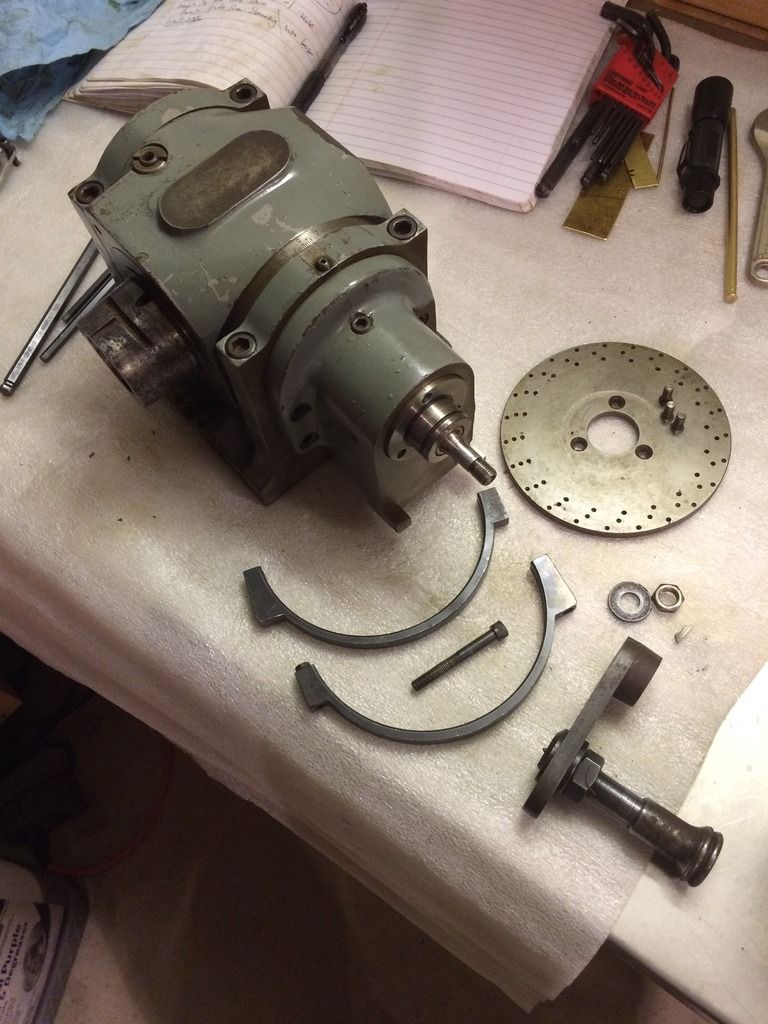
Step 2: Remove 4 Socket Head Cap Screws (SHCS)and oil plug. Put some oil in here to lubricate the drive handle shaft.
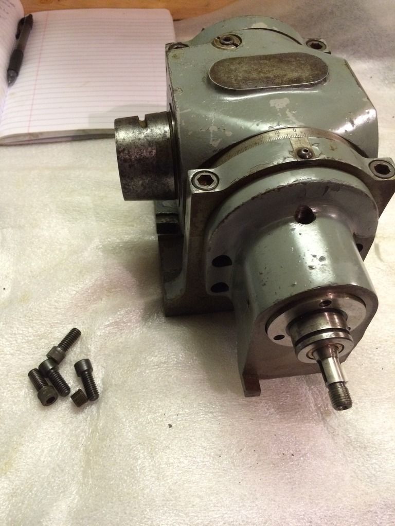
Step 3: Remove drive side casting from remainder of head.
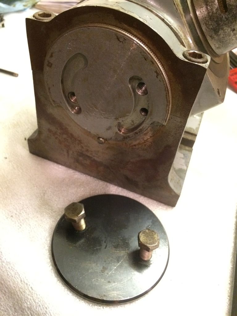
Step 4: On opposite side of head remove 2 hex head screws, black cover, and silver plate with limit cams. The function of this cam plate is to prevent the nose of the head from being able to be slammed into the base of the head when adjusting the head angle. When re-assembling, angle the head down -20 degrees, adjust the cam to be line to line with the edge of the bolt holes. Assemble the cover and tighten down the bolts. Now when the head angle is adjusted, it can't go further than -20 degrees, the cam bottoms out on the screw preventing the nose from impacting the base.

Step 5: Remove 2 SHCS from the caps on each side of the uprights from the base supporting the head. The caps can be removed and the head can be removed from the base.
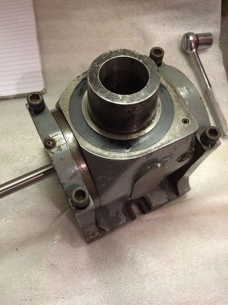
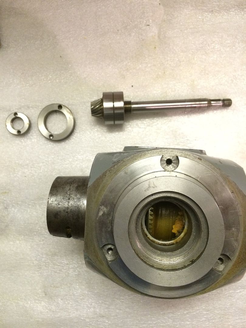
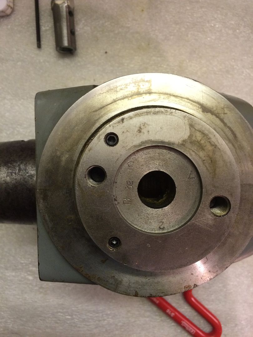
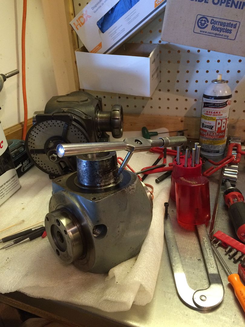
Step 6: Remove 3 screws and remove numbered ring.
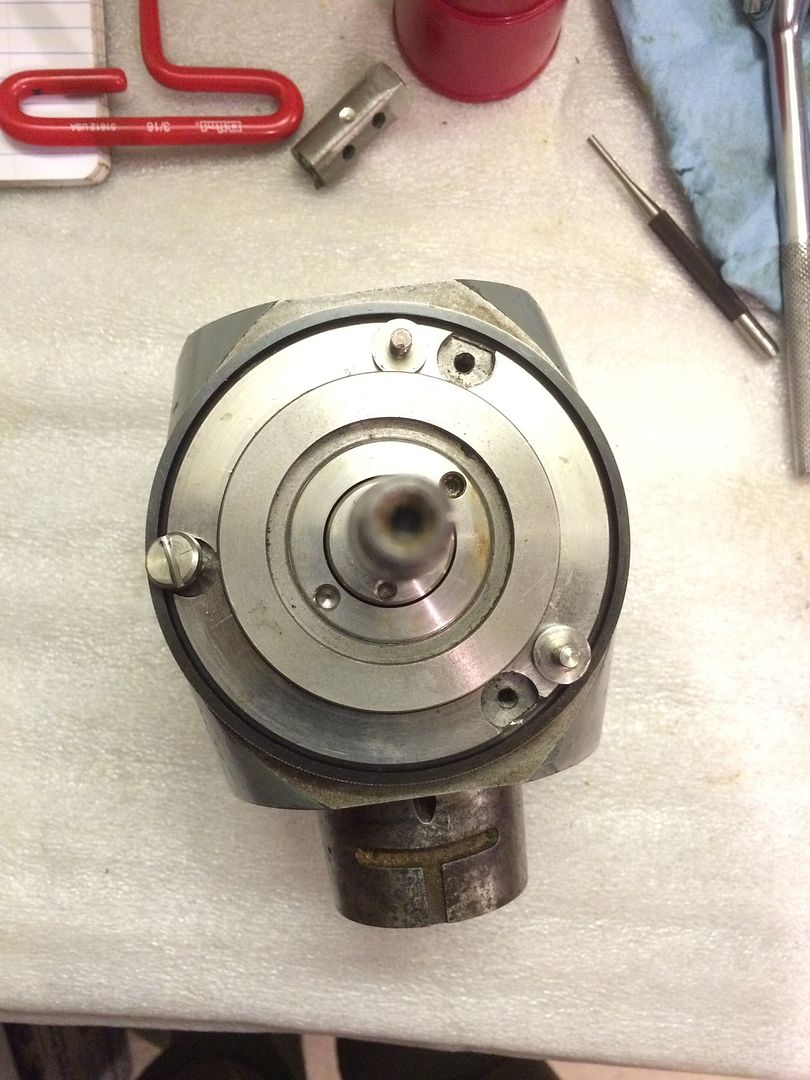
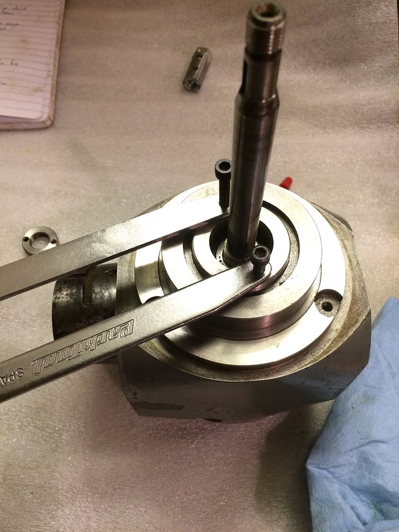
Step 7: Use adjustable pin spanner wrench to remove bushing retaining bearing and input pinion shaft.
Step 8: Remove pinion shaft
Step 9: On tapered spindle end- remove 2 set screws and 2 brass lock pins below. These lock onto the threads of the plugs which retain the spindle lock assembly.
Step 10: On the side opposite the input pinion there are 2 sets of stacked set screws in the small holes. The deeper ones key the bushings which lock the spindle. The upper ones just lock the position of the lower ones.
Step 6: Remove 3 screws and remove numbered ring.

Step 7: Use adjustable pin spanner wrench to remove bushing retaining bearing and input pinion shaft.

Step 8: Remove pinion shaft

Step 9: On tapered spindle end- remove 2 set screws and 2 brass lock pins below. These lock onto the threads of the plugs which retain the spindle lock assembly.

Step 10: On the side opposite the input pinion there are 2 sets of stacked set screws in the small holes. The deeper ones key the bushings which lock the spindle. The upper ones just lock the position of the lower ones.

Step 11: Remove the spindle lock parts. The spindle lock consists of a shaft with a righ and left hand thread on it. Threaded to it are 2 bushings. These bushings are restricted to axial motion due to the key slots and the set-screws just removed. The is a slotted collar around the spindle. When the input shaft is rotated, it causes the lock busings to move axially towards each other, clamping each leg of the lock collar and restraining the spindle.
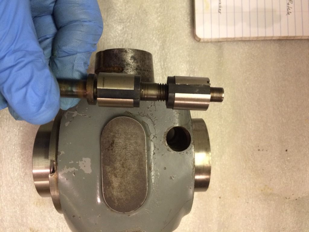
I sanded down a threaded coupling to make a tool to unthread the top and bottom retaining bushings.
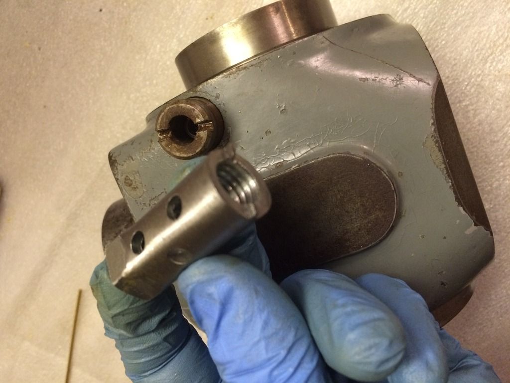
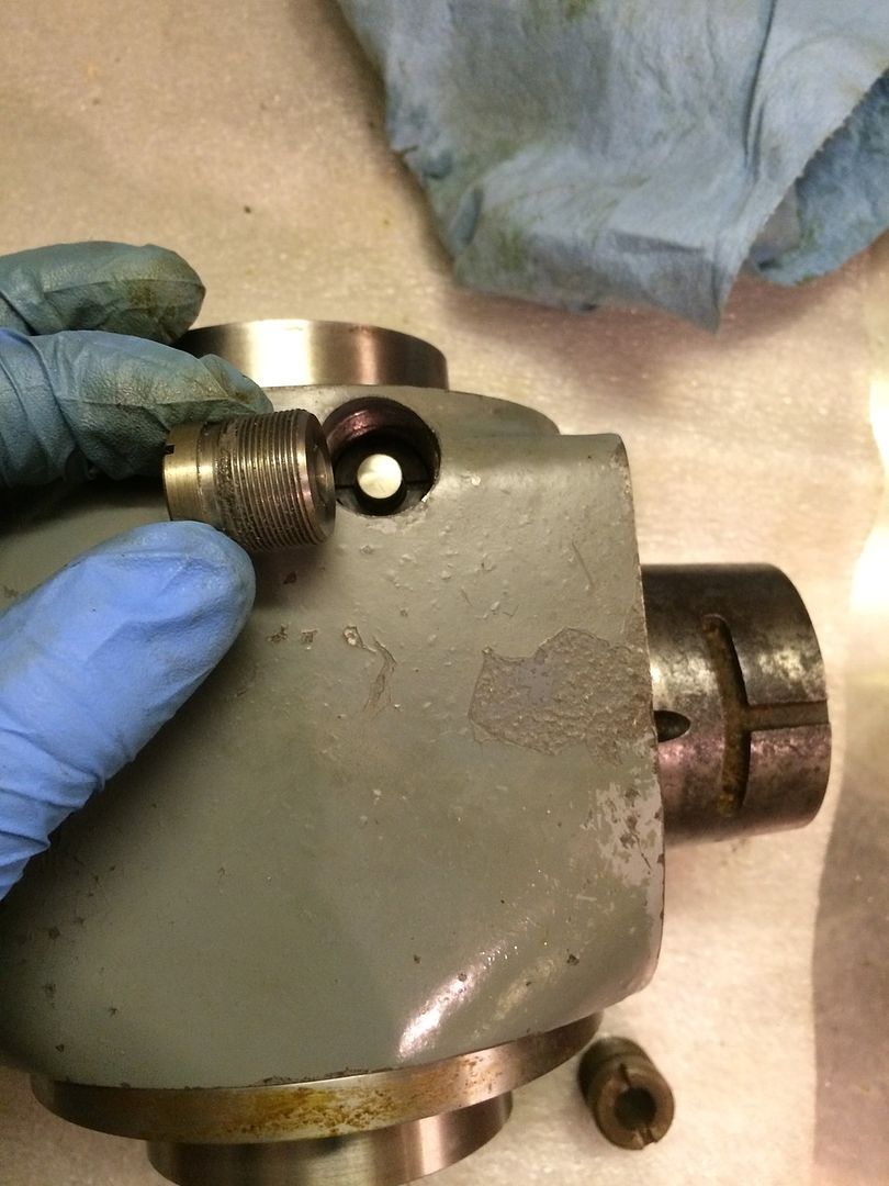
Unthread the bottom lock bushing from the shaft using the custom tool, then pull the threaded shaft and top lock plug from the head. the lock assembly is shown below.
Step 12: Remove the spindle. Start by removing the snap ring at the back of the spindle.
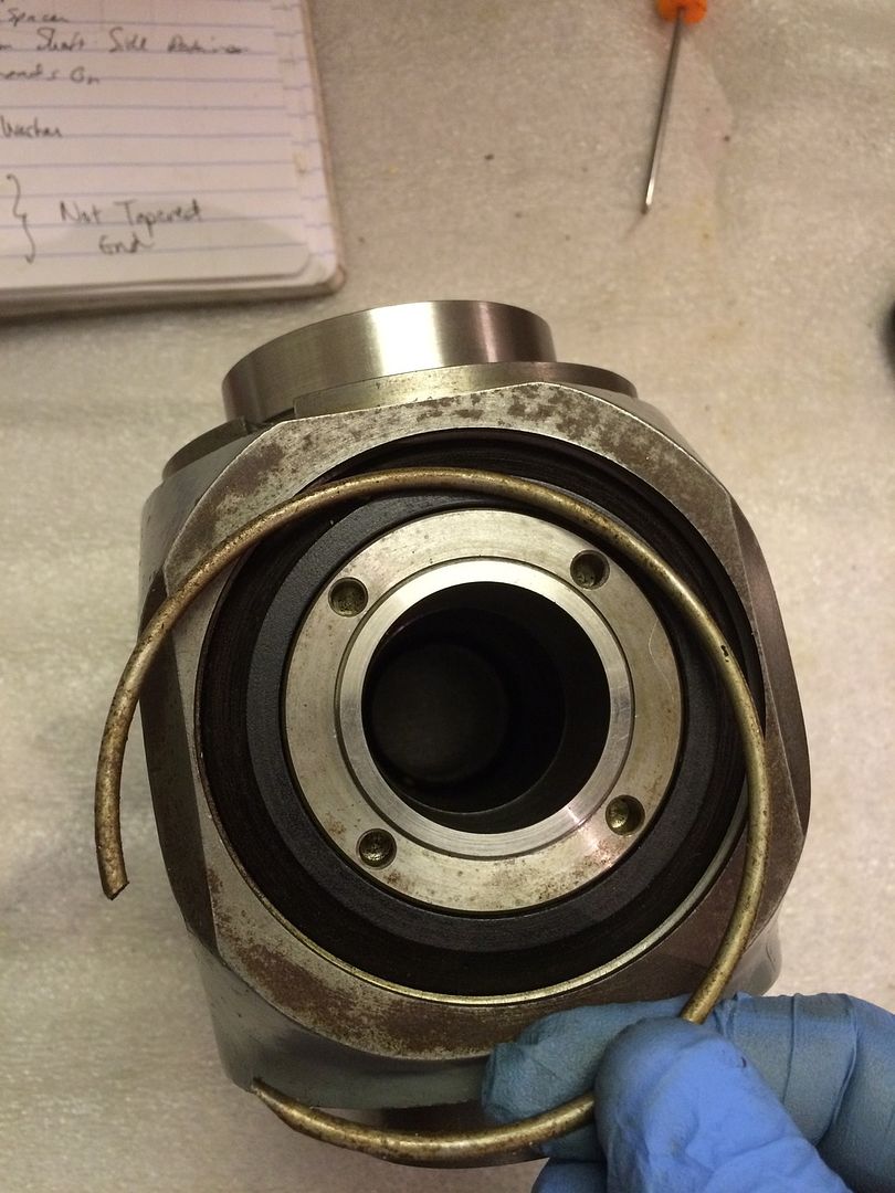
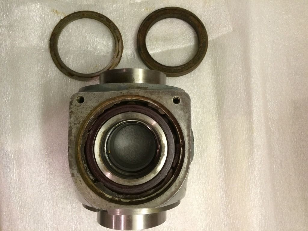
Use the spanner to remove the bushing that retains the spindle and preloads the spindle bearings. Once the bushing is removed, the tapered black plastic (Acetyl?) busing with the felt bushing and steel washer below it can be removed.
I sanded down a threaded coupling to make a tool to unthread the top and bottom retaining bushings.


Unthread the bottom lock bushing from the shaft using the custom tool, then pull the threaded shaft and top lock plug from the head. the lock assembly is shown below.

Step 12: Remove the spindle. Start by removing the snap ring at the back of the spindle.

Use the spanner to remove the bushing that retains the spindle and preloads the spindle bearings. Once the bushing is removed, the tapered black plastic (Acetyl?) busing with the felt bushing and steel washer below it can be removed.

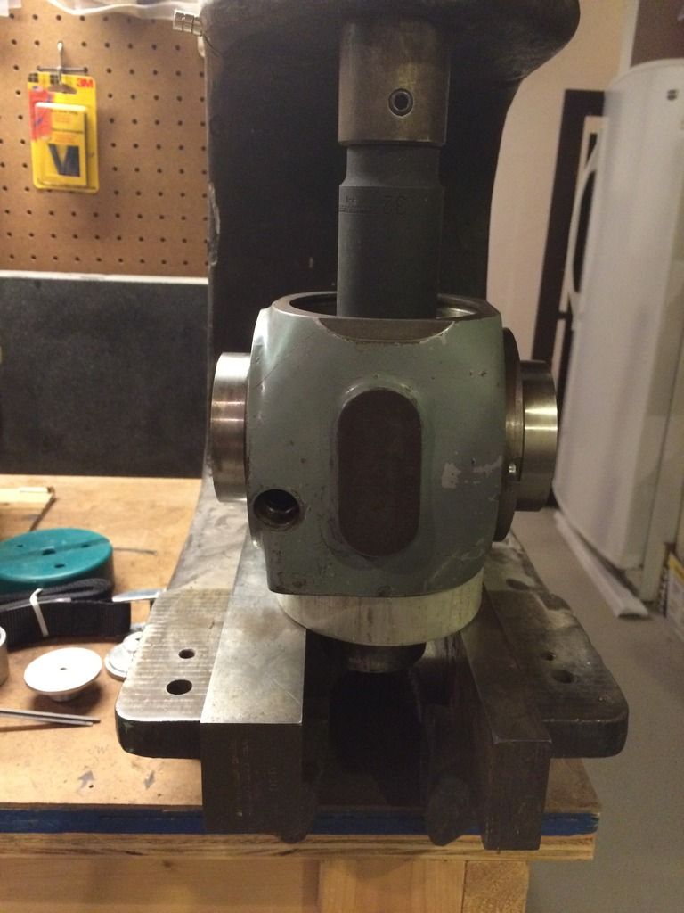
Step 13: Support the inner race of the front (tapered spindle side) bearing and press the spindle out from the back to the front.
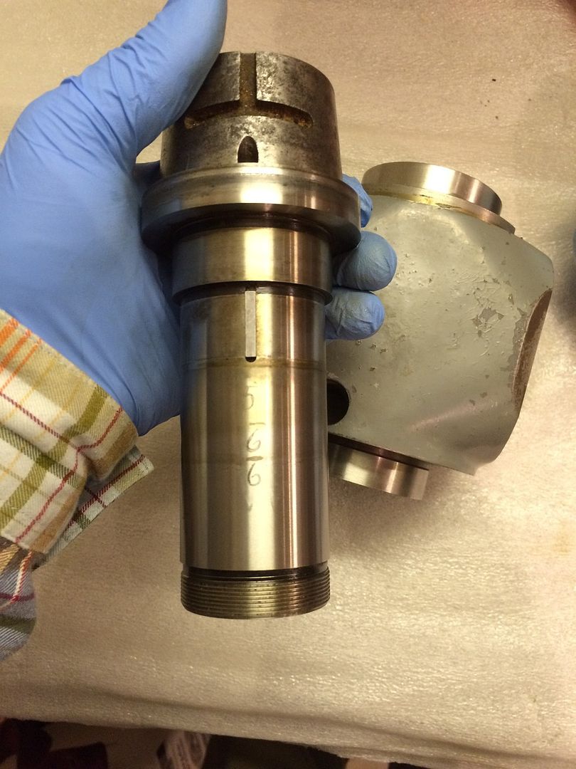
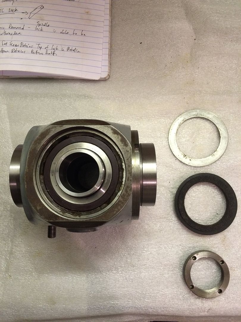
Step 14: With the spindle removed the front Acetyl bushing containing the felt washer below, and the steel washer below can be removed.
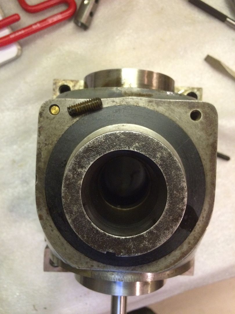
Step 15: You can remove the 5c lock pin by removing the long set-screw from the nose and the lock-pin beneath. My setscrew was rusted in and stripped and had to be drilled and Easy-outed.
The spindle is keyed to the large (spirol?) bevel gear. To remove the large bevel gear, the spacer, the lock collar, the spindle bearings would need to be removed. I did not remove the bearings or the remaining internals.


Step 14: With the spindle removed the front Acetyl bushing containing the felt washer below, and the steel washer below can be removed.

Step 15: You can remove the 5c lock pin by removing the long set-screw from the nose and the lock-pin beneath. My setscrew was rusted in and stripped and had to be drilled and Easy-outed.

The spindle is keyed to the large (spirol?) bevel gear. To remove the large bevel gear, the spacer, the lock collar, the spindle bearings would need to be removed. I did not remove the bearings or the remaining internals.
sfriedberg
Diamond
- Joined
- Oct 14, 2010
- Location
- Oregon, USA
Excellent photo series and instructions for the disassembly. I no longer have many excuses not to clean up mine...
Similar threads
- Replies
- 5
- Views
- 437
- Replies
- 6
- Views
- 512