What's new
What's new

Help, choosing best setup for milling pockets in sheet metal box.

El Mustachio

Hot Rolled
Joined
Jul 28, 2010
Location
Eastern Washington, USA
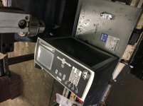
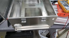
We build an operator control panel for our equipment that requires milling a pocket out of a sheet metal box for a joystick. The most trouble seems to come from trying to hold the workpiece as rigidly as possible. It's already formed into a box shape before it gets here.

When I first made these, I actually plasma cut the pockets. It worked, but it was messy, required some careful torch alignment, and just left a lot of mess to clean up before the wiring could be added.

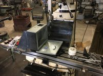
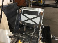
Milling the slot seems to leave a better finish, less likely to snag the wiring, but only if I can keep the chatter down. The box has (4) holes in the bottom panel (perpendicular to the face I need to mill). I tried mounting it to a large channel (scrap truck frame) that was secured to the milling table. That worked for a few runs, but was still prone to vibration. This last time I made a fixture to hold it on 4 faces of the box, that's getting better. The channel mount held the box on one face. But even with the new fixture, I still fight vibration. If I run the spindle 200 rpm or less I can keep the vibration at a minimum.

My guess is that because of the preformed box shape, I'm probably going to never fully get rid of the vibration. I'm just looking for someone else to put eyes on this and see if I'm missing an obvious solution. Thanks in advance, pics below.
IMG_6173.jpg
IMG_6174.jpg
IMG_6175.jpg
IMG_6178.jpg
 
We build an operator control panel for our equipment that requires milling a pocket out of a sheet metal box for a joystick. The most trouble seems to come from trying to hold the workpiece as rigidly as possible. It's already formed into a box shape before it gets here.

When I first made these, I actually plasma cut the pockets. It worked, but it was messy, required some careful torch alignment, and just left a lot of mess to clean up before the wiring could be added.

Milling the slot seems to leave a better finish, less likely to snag the wiring, but only if I can keep the chatter down. The box has (4) holes in the bottom panel (perpendicular to the face I need to mill). I tried mounting it to a large channel (scrap truck frame) that was secured to the milling table. That worked for a few runs, but was still prone to vibration. This last time I made a fixture to hold it on 4 faces of the box, that's getting better. The channel mount held the box on one face. But even with the new fixture, I still fight vibration. If I run the spindle 200 rpm or less I can keep the vibration at a minimum.

My guess is that because of the preformed box shape, I'm probably going to never fully get rid of the vibration. I'm just looking for someone else to put eyes on this and see if I'm missing an obvious solution. Thanks in advance, pics below.

View attachment 197133
View attachment 197134
View attachment 197135
View attachment 197136

.
.
i usually clamp sheet metal to plywood or masonite and to thick aluminum. if i cut into wood it is no big deal
 
https://www.automationdirect.com/ad...gement_-z-_Lighting/Enclosures/Custom_Cutouts

For a fixture I would be trying to clamp the surface you are actually milling as best you can and also stabilize the other panels so they can't start to sing.

One part I make is a cast aluminum housing. It sings like no other even in a well supporting fixture. I added a long flimsy steel clamp that pushes on the center of the largest flat surface and it didn't really change. Then I put a thin piece of hardwood under that clamp. Problem solved. No more chatter.
 
Instead of making all those holes and details into the side of the Hoffman box,
plasma cut out the side, leave 3/4" or so all around for a bolt flange.

Have a laser shop make the whole plate for you with the holes, slots, ect. along
with the flange bolt holes.

Simply bolt your new "side panel" over the large rectangular hole, drilling the clamping bolt holes
into the Hoffman, using the laser cut panel as a template.
 
https://www.automationdirect.com/ad...gement_-z-_Lighting/Enclosures/Custom_Cutouts

For a fixture I would be trying to clamp the surface you are actually milling as best you can and also stabilize the other panels so they can't start to sing.

One part I make is a cast aluminum housing. It sings like no other even in a well supporting fixture. I added a long flimsy steel clamp that pushes on the center of the largest flat surface and it didn't really change. Then I put a thin piece of hardwood under that clamp. Problem solved. No more chatter.

I'll try clamping a piece of wood to the inside wall of the box, directly under the pocket, on the next run. I like the Automation Direct link. Up to this point our design has changed enough that we can't yet farm it out. I think the design is pretty close to it's final revision though, I'll definetely look at what Automation Direct can do on this part. Thanks.
 
It's not worth doing it yourself. Contact one of the enclosure companies and order what you need.

(posted before I saw your last post)
 
I'd probably holesaw the corners to the radius you want. Then stab around the cutout with something like a 1/4" endmill leaving about .030 on the pocket. Finish pocket to size with something like a 1/8" endmill.
 
Call me a spoil sport if you like, but: The workmanship you are achieving right now looks really good. As long as it isn't _unsafe_, who cares if there is a little chatter? I have to say overdesigning applies to fixtures as well as products. I say, keep up the good work!

LM
 
I'd use a piece of thick ply or pine up under the top plate held in place and jacked up with wood blocks and folding wedges - easy peasy.

If not already, switch to an HSS end mill, keeping the dia small as it reduces the cutting forces when slotting ........preferably a slow helix or even down cutif you can find one.

And please tell us you're not holding the EM in that drill chuck ;)
 
And please tell us you're not holding the EM in that drill chuck ;)

Easy, no I'm not holding the end-mill with that drill chuck. The holes for toggle switches, LED's, and cord reliefs are easier to cut with annular cutters rather than twist drills. That's what the jacobs chuck is there for in the pic. Except for the really small stuff, all our end-mill work is done with set-screwed end-mill holders. Some of the tiny stuff I'll mount in an R8 collet, but for the most part the collet rack just collects dust.
 
That looks like a candidate for a nibbler to me. Maybe make a template that goes over the top and then run a nibbler around the box shape. Just occured to me - can you get a nibbler head for a CNC mill?

(I agree with the comments above about bolting backing to it, or sending the entire thing out if possible.)
 
that just isn't a milling job, you should be able to find someone who has a laser with a Z that can accommodate the box, or get it cut out of a sheet and attach that onto the box, after cutting out most of the side.

seriously, a laser can blast that out literally in seconds.

this is kinda like watching a carpenter try to
mend pottery with a hammer... :nutter: :cheers:


Prima Power Platino Fiber with 4kw Laser Cutting Demonstration - YouTube
 
The Mustache,

I've got a number of low volume products that require we put holes in off the shelf enclosures. Customized from the manufacturer enclosures would be great, but the lead time doesn't work for us.

Where possible, I do a big hole in the off the shelf enclosure and then bolt on a plate with the connectors or weird cutouts. On one product in a 16 ga stainless box, I took it from ~13 holes of various sizes to two drilled holes with two spot welded plates. Fab time went from about an hour of drilling and deburring and cleaning to about 15 minutes. Like you, I've found the annular cutters work the best for getting clean round holes. After trying many things for the last 8 years, I'm pretty happy with Greenlee's hole cutter and arbor:
Amazon.com: Greenlee 645-2-1/2 Quick Change Stainless Steel Hole Cutter, 2-1/2-Inch: Home Improvement
Greenlee 645-22 Quick Change Arbor for Sizes 2-3/8 Through 3-Inch, 1/2-Inch Shank - Slotting Cutter Arbors - Amazon.com

20170426_081327.jpg
20170426_081550.jpg
 
Last edited:
Many lasers do not have that much z above the slats. But slats are easy to remove to provide plenty of room to fit that box inside. Box can rest on a shelf and the laser will not care if it is exactly level with the slats. The nozzle reads the surface of the material. Even to the point of cutting diamond plate.
 
I like the slab of wood and bottle jack idea, a little tension pushing up should help enough with the chatter to get the job done.
 
I have done a lot of electronic enclosures, usually in small quantities, often one offs. Most of the ones I did were aluminum and with thicknesses from 0.032" up to 0.125". Some were steel and those were 0.062" thick or less. That is about what I call sheet metal. But I know that some will call heavier gauges sheet metal.

If this is really what I call sheet metal there are several options that I would consider. First, it is almost always easier to punch sheet metal than to mill it. My exceptions to this would be really odd shapes or really narrow ones, like a 1/4" wide slot that runs for several inches in length. Chassis punches come in a wide variety of sizes and shapes, including round and square. I have a collection of around 35 or 40 of them and they are my first choice for aluminum up to 1/8" and steel up to about 0.050". You just drill a center hole for the draw stud and punch the hole. I have used successive punches with a square punch to form larger sizes of holes or odd rectangular sizes. This could work with your large, almost square hole. First drill the needed pilot holes and then punch to the outline in steps. This method would produce a clean edge, but is obviously not suited for any volume production.

Another method that suggests itself to me would be to make a pair of wood braces for each side of your enclosure and sandwich it between them with some threaded rod and nuts. That should brace it fairly well against vibration. I would construct it from 3/4" plywood or particle board and use triangular braces between the vertical sides and the horizontal base pieces. Those base pieces can have mounting holes for easy assembly to the mill's table. I would use the glue and screw method for constructing these braces. Then back up the cut area with a wood scrap, probably fastened with wood screws in holes drilled in the area you seem to have marked for the corner slots. And mill away. This will need more clean-up than the punches, but will probably go faster. OK, REVISION: I see you already have a metal brace for ONE side. Just make a plywood cover for the second side and fasten it with the threaded rod as I suggest. That will brace the other side where the door is open. The threaded rod would be just outside of the box.


One final thought would be that your joystick will probably have a built in bezel which will cover the cut edge. So, a perfectly straight and accurate cut is not needed. You could print a layout on self-adhesive paper and paste it on. After drilling four corner holes in pre-marked positions, use a hand held saber saw to cut the outline. It will even cut to the corners so the only filing needed would be to cleanup the ragged edge. The paper label will protect the finish from the saber saw and it can be easily removed by spraying with WD-40 and letting it set for 5 or 10 minutes.

You should carefully consider the volume of these that you will be making as that will strongly influence your choice of methods. One per month hardly warrants much work on the fixtures while 100 a day would demand the best possible fixture.


Back
Top